
Shape inspection apparatus, and shape inspection method

A technology for inspecting devices and three-dimensional shapes, applied in special data processing applications, instruments, electrical digital data processing, etc., can solve problems such as selection and designation errors, omissions of shape constituent elements, etc., to achieve rapid judgment processing, shorten judgment time, eliminate adverse effects

Active Publication Date: 2009-05-20
FUJIFILM BUSINESS INNOVATION CORP
View PDF1 Cites 2 Cited by
  • Summary
  • Abstract
  • Description
  • Claims
  • Application Information

AI Technical Summary

Problems solved by technology

Therefore, especially when the shape of the product is complicated, some human errors may occur, such as errors in selection and designation or omissions of shape constituent elements

Method used


Image

  • Shape inspection apparatus, and shape inspection method
  • Shape inspection apparatus, and shape inspection method
  • Shape inspection apparatus, and shape inspection method

Examples


Embodiment Construction

[0032] Hereinafter, a shape inspection apparatus, a shape inspection method, and a shape inspection program according to the present invention will be described with reference to the accompanying drawings.

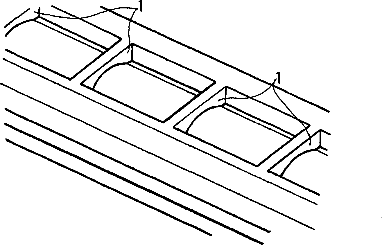
[0033] Here, the determination as to whether the rib structure portion satisfies the shape condition is exemplarily described. Here, the rib structure portion is a convex-shaped portion in a product member having a three-dimensional shape.

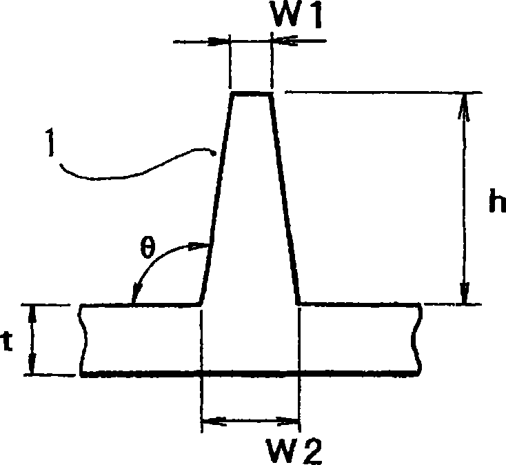
[0034] Figure 1A and Figure 1B is an explanatory diagram showing a rib structure portion as a specific example of a shape portion subjected to determination processing.

[0035] like Figure 1A As shown, a product member having a three-dimensional shape generally has a rib structure portion (hereinafter simply referred to as "rib") 1, which is a convex shape portion for preventing deflection of the member or ensuring strength (rigidity) of the member.

[0036] However, when the rib 1 has an excessively large height or thickness, so...


PUM


Abstract

A shape inspection apparatus includes a shape display unit that displays a three-dimensional shape specified by three dimensional shape data on a screen; a direction designating unit that specifies a drawing direction in molding the three-dimensional shape on the screen; a face designating unit that specifies one face of a protruding or recessed shape portion of the three-dimensional shape on the screen; a dimension calculating unit that calculates a shape dimensional value of the shape portion based on the specified drawing direction and the specified one face; and a determination unit that determines whether or not the shape portion having the shape dimensional value satisfies a shape condition by comparing the calculated shape dimensional value with a standard value.

Description

technical field [0001] The present invention relates to a shape inspection device and a shape inspection method. Background technique [0002] In product design using a CAD (Computer Aided Design) system, it is necessary to judge whether or not the product shape represented by the CAD model contains abnormal parts. When the product has an abnormal portion, it is necessary to change the product shape design (for example, refer to Patent Document 1 (JP-A-2005-275596)). Here, the abnormal portion refers to a portion that is difficult to process when a mold is produced from a CAD model, or a vulnerable portion of a product obtained from the mold. That is, the abnormal portion refers to a portion that is not suitable for a product, such as, for example, a sharp protrusion and a sharp recess, and the like. [0003] For example, as disclosed in Patent Document 1, in order to judge whether or not the product shape represented by the CAD model contains abnormal parts, it is necessa...

Claims


Application Information

Patent Timeline
Patent Type & Authority Applications(China)
IPC IPC(8): G06F17/50
CPCG06K9/00476G06V30/422
Inventor 中里博昭萩原正明沼内寿浩竹崎克己
Owner FUJIFILM BUSINESS INNOVATION CORP
Learn More