Electric power generator, method for generating electric power, and motor

An electric motor and generator technology, applied in electrical components, electromechanical devices, etc., can solve the problem of incremental efficiency exceeding 1, and achieve the effects of simple structure, reducing back torque, and increasing incremental efficiency

Inactive Publication Date: 2009-05-20
白川义章
View PDF0 Cites 8 Cited by
  • Summary
  • Abstract
  • Description
  • Claims
  • Application Information

AI Technical Summary

Problems solved by technology

In other words, even when the system efficiency is less than 1, sometimes the incremental efficiency exceeds 1

Method used


Image

  • Electric power generator, method for generating electric power, and motor
  • Electric power generator, method for generating electric power, and motor
  • Electric power generator, method for generating electric power, and motor

Examples


Embodiment Construction

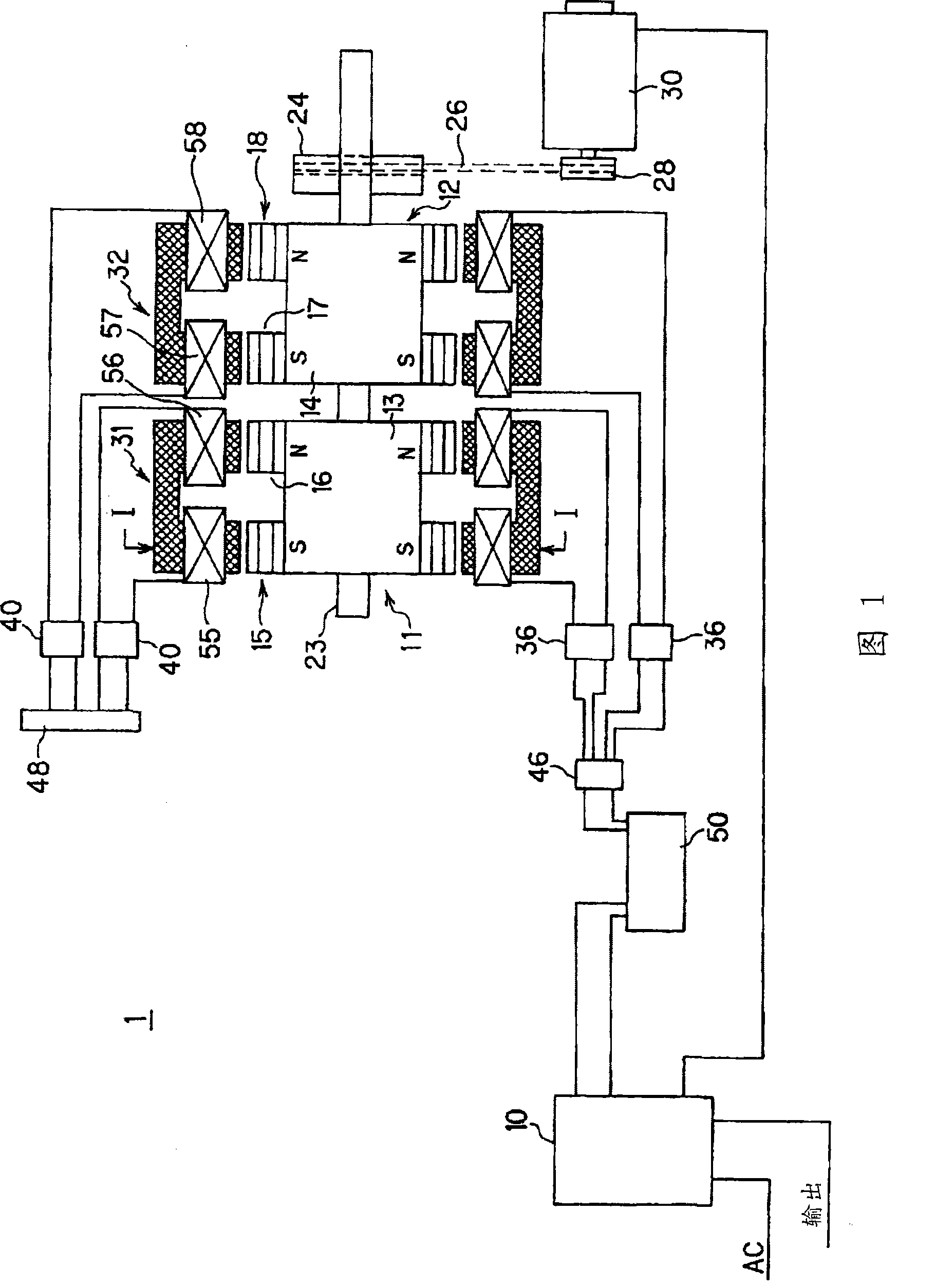
[0054] FIG. 1 shows the structure of a generator 1 according to an embodiment of the present invention. As shown in this figure, the generator 1 includes: a control device 10 for controlling the power generation program, a first rotor 11 and a second rotor 12, and a first stator 31 and a second stator arranged around the rotors 11 and 12 respectively. 32. A DC motor 30, an electric double layer capacitor 50 for storing the electric energy output by the stator.

[0055] The first rotor 11 and the second rotor 12 are rotatable together using a common main shaft 23 as a rotation axis. A pulley 24 is installed on the main shaft 23 , and a belt 26 is arranged between the pulley 24 and the pulley 28 installed on the output shaft of the DC motor 30 . Therefore, the first rotor 11 and the second rotor 12 are rotated together by the rotation of the DC motor 30 .

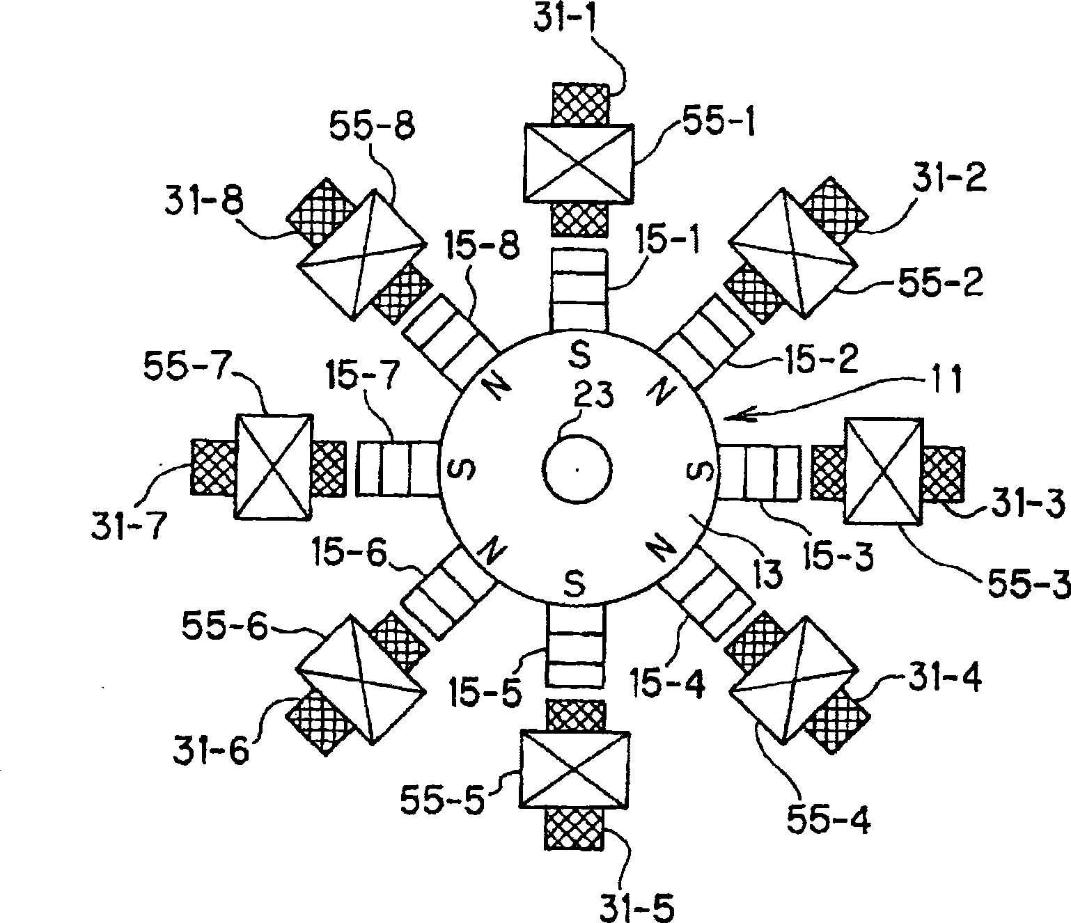
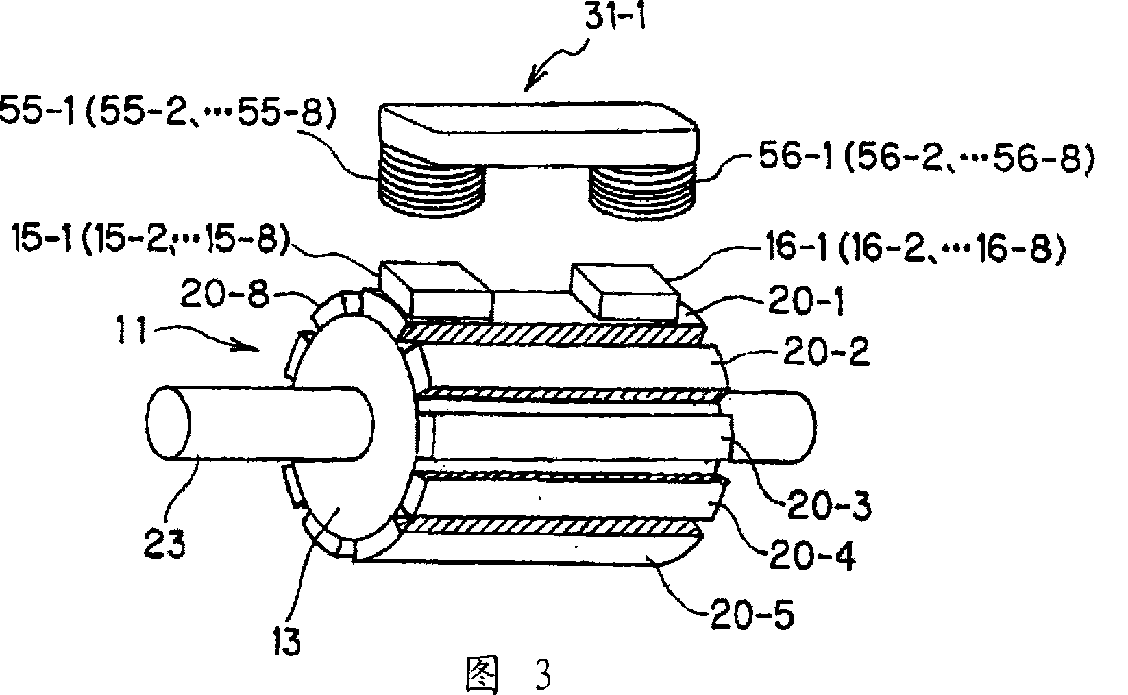
[0056] The first rotor 11 is axially equipped with two rows of magnet rows side by side: a first magnet row 15 and a seco...


PUM


Abstract

An electric generator 1 according to the present invention comprises a controller 10, rotors 11, 12, stators 31, 32 and an electrically-driven motor 30. Two rows of magnets 15 and 16 aligned axially side by side are mounted on the rotor surface such that respective magnetic poles of respective magnets are inversely oriented alternately along the circumferential direction and the magnetic poles are different from each other in a pair of two axially aligned magnets. Each of the stators 31, 32 comprises a plurality of stator blocks, wherein a core of each block has two core end portions which can be placed in opposite to a pair of magnets of the rotor and a core intermediate portion and wherein each of the core end portions is equipped with coil 55, 56, 57, 58 wound around the core end portion. The stator block includes a stator block for electric generation, which is connected to a capacitor 50 via a bridge diode 36 and an electric generation pulse circuit 46 and a stator block for motor action, which is connected to a motor pulse circuit 48 via a bridge diode 40. The motor pulse circuit 48 comprises an electric short-circuit switch. According to the present invention, the incremental efficiency of the electric generator can be remarkably improved.

Description

technical field [0001] The invention relates to a generator, a method of generating electricity and an electric motor. Background technique [0002] In the current power generation system, the rotor of the generator is rotated using external energy (hydraulic power, thermal power, atomic power, wind power, etc.), and the method of converting the mechanical rotational energy into electrical energy is dominant. Existing generators generally include: a rotor equipped with a plurality of permanent magnets, a stator arranged around the rotor and composed of a plurality of coils, a sensor for detecting the rotation angle of the rotor, and an It is a switching circuit that switches the wiring mode of the stator coil winding so that the stator coil generates an induced electromotive force. In the existing generator, multiple coils of the stator are connected to each other, and the electricity and magnetism are not independent. [0003] The power generation principle of this mainst...

Claims


Application Information

Patent Timeline
Patent Type & Authority Applications(China)
IPC IPC(8): H02K16/00
CPCH02K53/00
Inventor 生越诚
Owner 白川义章
Why Eureka
Try Eureka