Vane type revolving compressor

A rotary compressor and vane-type technology, applied in the field of compressors and vane-type rotary compressors, can solve the problems of high friction power consumption and increase of compressor shaft power, so as to reduce shaft power consumption, friction loss and leakage loss. , with smooth effect

Inactive Publication Date: 2009-05-27
ZHEJIANG HONGYOU AIR COMPRESSOR MFG +1
View PDF0 Cites 6 Cited by
  • Summary
  • Abstract
  • Description
  • Claims
  • Application Information

AI Technical Summary

Problems solved by technology

[0003] Aiming at the above-mentioned problems existing in the current vane compressors with a rotary column structure, the present invention provides a vane rotary compressor, which aims to effectively solve the problems caused by the high frictional power consumption between the flat slots of the rotary column and the vanes, resulting in the axial work of the compressor. additional questions

Method used


Image

  • Vane type revolving compressor
  • Vane type revolving compressor
  • Vane type revolving compressor

Examples


Embodiment Construction

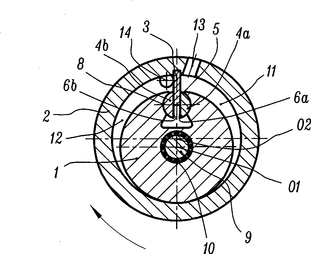
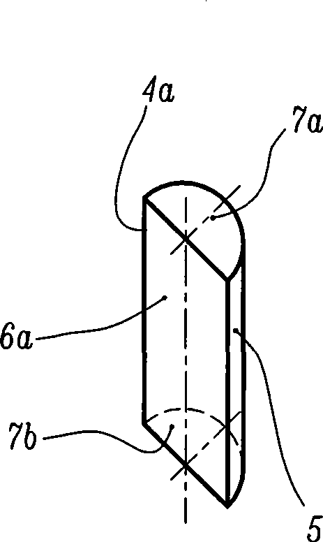
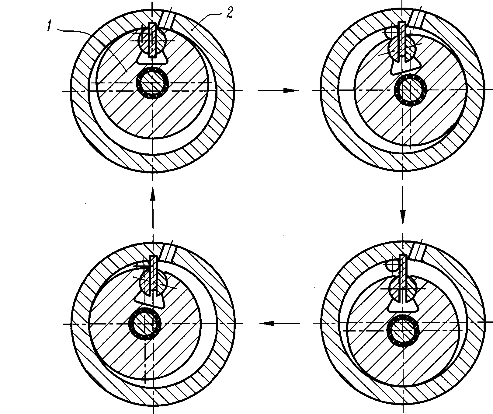
[0014] figure 1 with figure 2 A schematic structural view of an embodiment of a vane type rotary compressor of the present invention and an axonometric view of a slider are respectively shown. In this embodiment, the vane rotary compressor includes a rotor 1, a cylinder 2, a vane 3, a first slider 4a, a second slider 4b, and an end cover (not shown); the rotor 1 has A cylindrical outer surface, the cylinder 2 has a circular hole-shaped inner surface, the blade 3 is flat and its two working surfaces are parallel to each other, and the first slider 4a and the second slider 4b have cylindrical arc-shaped arc surface 5, planar sliding mating surfaces 6a and 6b, two column end faces 7a and 7b parallel to each other and perpendicular to sliding mating surfaces 6a and 6b; the rotor 1 is biased in the cylinder 2, and the axis of the rotor 1 is The rotor axis O1, the axis of the cylinder 2 is the cylinder axis O2, the rotor axis O1 and the cylinder axis O2 are set parallel to each o...


PUM


Abstract

The invention relates to a rotary vane compressor, which comprises a rotor 1, a cylinder 2, a vane 3 and an end cover, wherein the rotor 1 offsets in the cylinder 2; the outside surface of the rotor 1 is in tangency and contact fit with the inner hole surface of the cylinder 2; the rotor 1 is provided with an arc groove 8; and the vane 3 is in fastened and sealed connection with the cylinder 2 and two lateral ends. The rotary vane compressor is characterized in that the compressor is provided with a first slide block 4a and a second slide block 4b which are arranged in the arc groove 8 and are in rotary fit with the arc groove 8; because two independent slide blocks are adopted to replace an integral rotary column, the matching surface among the first slide block 4a, and the second slide block 4b and the vane 3 can be processed and treated conveniently, including grinding and various surface treatments, so as to obtain high precision dimension, shape, position, surface coarseness, planeness, surface rigidity and the like. Therefore, the fit among the first slide block 4a, the second slide block 4b and the vane 3 is smoother, and friction loss and leakage loss are reduced, so as to be favorable for the reduction of shaft work consumption of the compressor.

Description

technical field [0001] The present invention relates to a compressor, in particular to a vane type rotary compressor, more specifically to a vane type rotary compressor including a rotary column structure. Background technique [0002] The vane compressor has the advantages of small size, light weight, simple structure and good dynamic balance performance, so it is widely used in the fields of air compression, refrigeration and air conditioning. However, the vane of the traditional vane compressor has relative motion relative to the cylinder and the end cover, so there must be a certain movement gap between them, which brings hidden dangers such as leakage loss and friction loss. In order to overcome the above-mentioned disadvantages of the traditional vane compressor, a rotary compressor that fastens and seals the vane, the cylinder and the end cover together has appeared, which includes the cylinder, the rotor, the vane, the end cover and the rotating column; The cylinder...

Claims


Application Information

Patent Timeline
Patent Type & Authority Applications(China)
IPC IPC(8): F04C18/344
Inventor 陈君立耿爱农李辛沫阮勤江王治超
Owner ZHEJIANG HONGYOU AIR COMPRESSOR MFG
Why Eureka
Try Eureka