

Cooling system of supersonic transducer
A technology of cooling system and transducer, which is applied in the direction of refrigerators, refrigeration and liquefaction, irreversible cycle compressors, etc. It can solve the problems of magnetic core heating and other problems, achieve the effect of convenient sealing, convenient disassembly and assembly, and reduce the loss of cooling capacity
- Summary
- Abstract
- Description
- Claims
- Application Information
AI Technical Summary
Problems solved by technology
Method used
Image

Examples
Embodiment 1
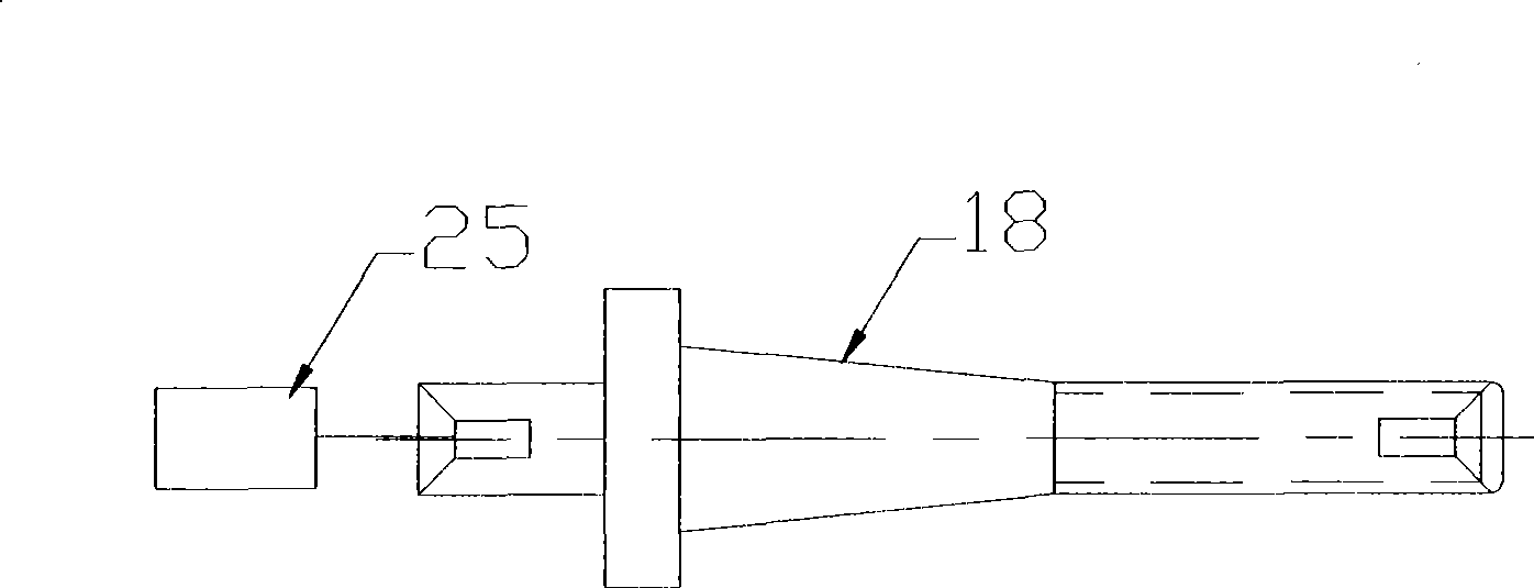
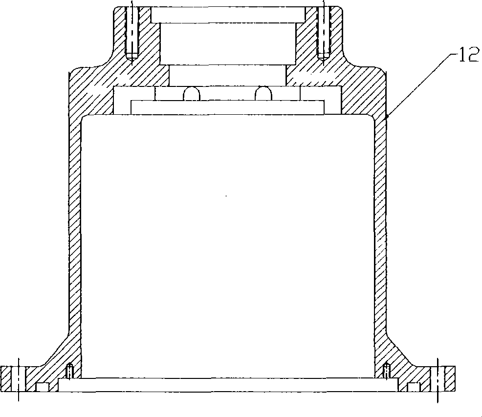
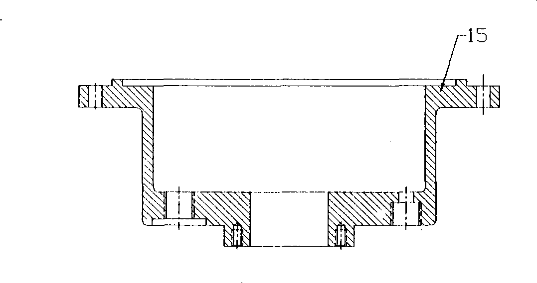
[0016] An ultrasonic transducer cooling system provided in this embodiment includes an ultrasonic transducer including a magnetic core assembly structure, and according to the magnetic core assembly structure contained in the ultrasonic transducer, the ultrasonic transducer magnetic core assembly Direct evaporative cooling of the inner and outer chambers. Such as Figure 5 Shown, implement a kind of ultrasonic transducer cooling system of the present invention, comprise compressor 20, condenser 21, throttling element 22, evaporator 23 and ultrasonic transducer 24, as Figure 4 As shown, the evaporator 23 includes a main shaft 1, an upper casing flange 2, an O-shaped sealing structure 3, a radial slot 4, an annular channel 5, a stud bolt 6, a magnetic core assembly 7, and a magnetic core inner Cavity 8, magnetic core outer cavity 9, rear cover plate 10, oil return slot 11, upper housing 12, decoupling ring 13, decoupling ring oil and gas hole 14, lower housing 15, liquid inlet...
PUM
 Abstract
Description
Claims
Application Information