
Digital weighing sensor capable of redounding and self-compensating deflection influence and method thereof

A load cell, digital technology, applied in the field of load cells, can solve the problems of inability to calibrate the load cell, adjust the headache, unable to guarantee the load cell, etc., to simplify the adjustment and correction work and maintenance work, and prevent errors.

Inactive Publication Date: 2009-05-27
HOLBRIGHT WEIGHING SYST
View PDF0 Cites 18 Cited by
  • Summary
  • Abstract
  • Description
  • Claims
  • Application Information

AI Technical Summary

Problems solved by technology

[0005] The current calibration method of the weighbridge station is to calibrate the value by applying a standard weight on the scale platform. The impact on the axis deviation of the load cell is only a general correction, and it cannot be accurately targeted at individual load cells. to calibrate the error
[0006] Taking the application of large tank scales as an example, the maximum weighing range of some tank scales is as high as several tons, tens of tons or even hundreds of tons, and it is difficult to use standard weights for calibration. There is not enough space for weights, so adjustment becomes a headache
Due to the difficulty of calibration, the allowable range of the measurement error of the tank scale is as high as 1 / 500, while the error of the weighbridge station is only 1 / 3000
[0007] In fact, any artificial installation work cannot guarantee that each load cell can be without the slightest deflection.

Method used


Image

  • Digital weighing sensor capable of redounding and self-compensating deflection influence and method thereof
  • Digital weighing sensor capable of redounding and self-compensating deflection influence and method thereof
  • Digital weighing sensor capable of redounding and self-compensating deflection influence and method thereof

Examples


Embodiment Construction

[0045] In order to make the above-mentioned purposes, features and advantages of the present invention more obvious and easy to understand, the preferred implementation advantages are specially cited below, together with the accompanying drawings, and the detailed description is as follows:

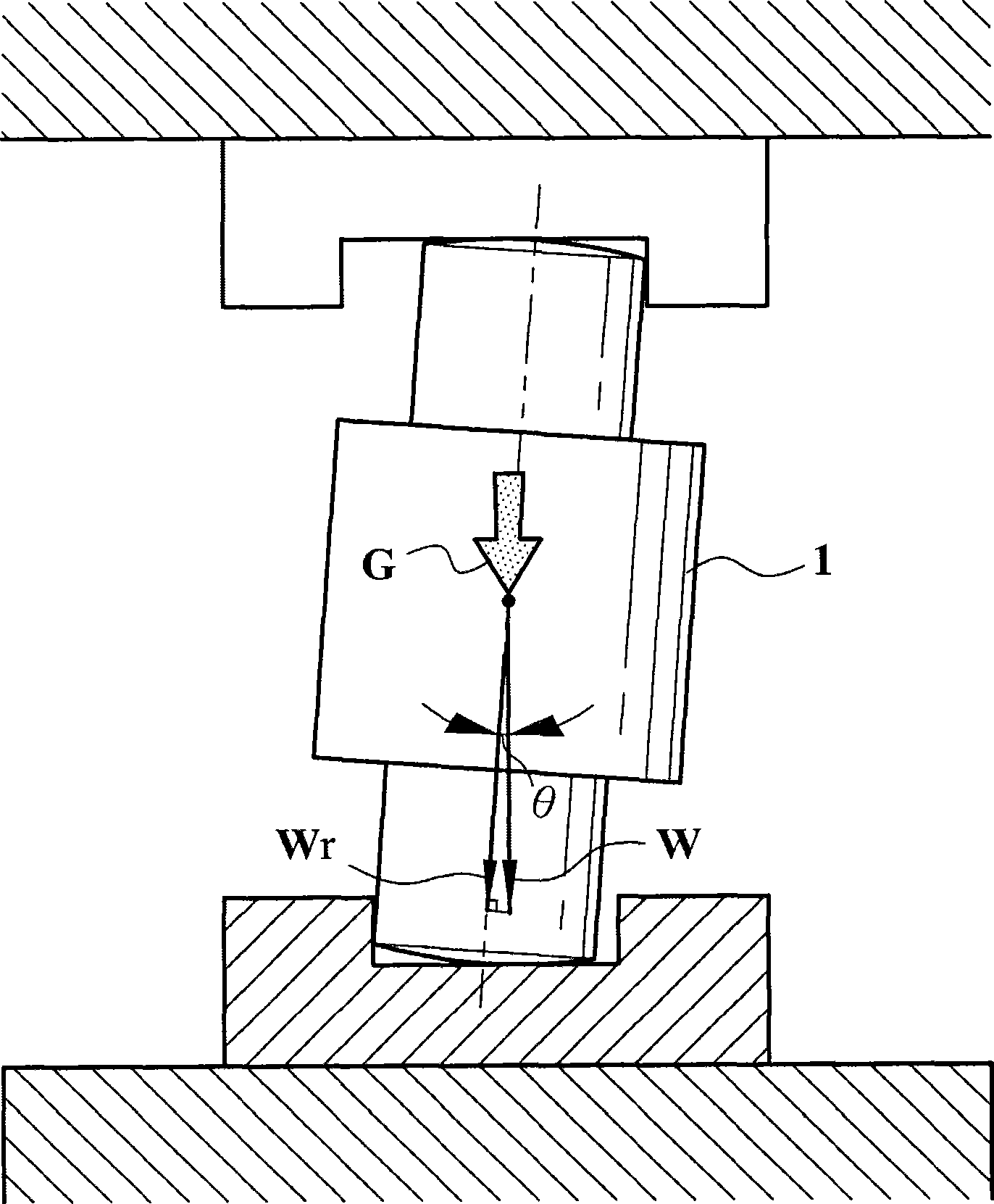
[0046] Such as figure 1 What is shown is a schematic diagram of a load cell 1 in a deflected state. Since there is an included angle θ between the axis and the gravitational direction G, the sensed value Wr is smaller than the actual weighed weight.

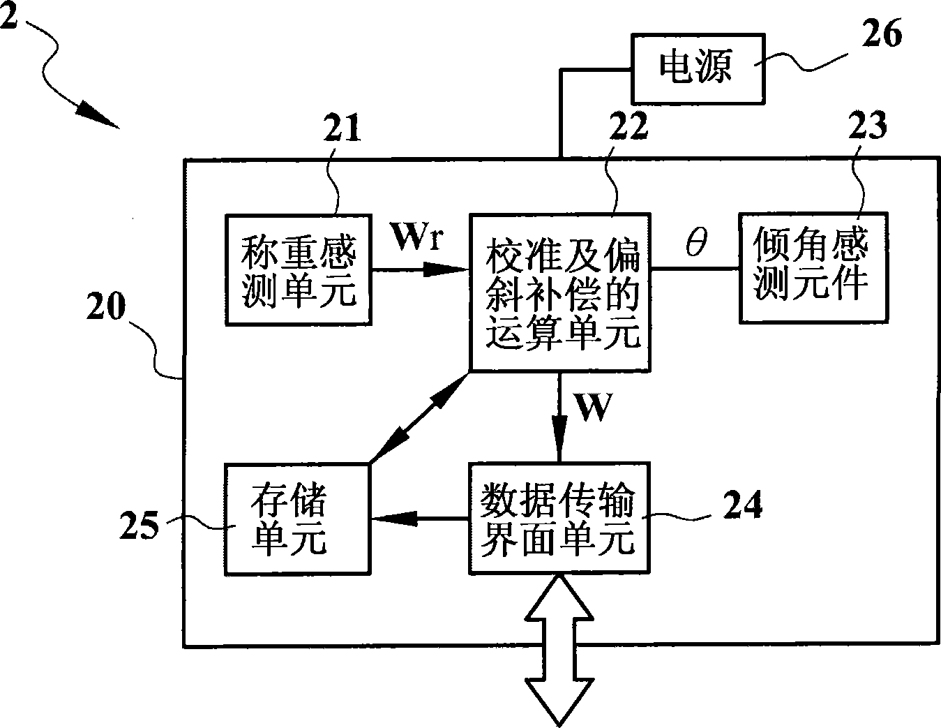
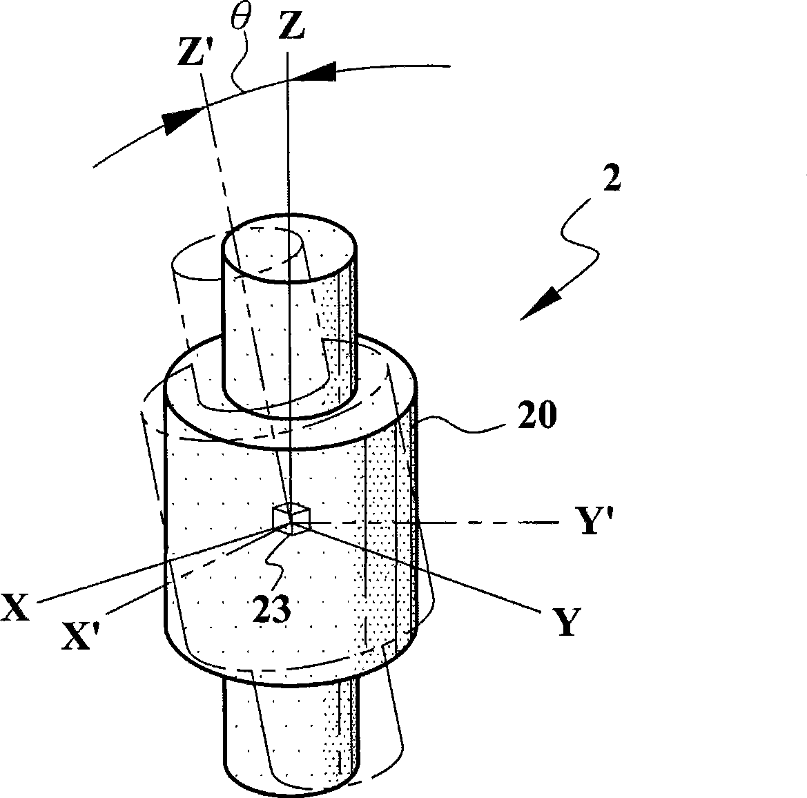
[0047] Such as figure 2 As shown, it is a digital load cell 2 of the present invention, including at least one load sensing unit 21, a calibration and deflection compensation calculation unit 22, and an inclination angle sensing element 23 installed in a casing 20. 1. A data transmission interface unit 24, a storage unit 25 and a power supply 26 are electrically connected to each other to measure the weight of an object and output a W dig...


PUM


Abstract

The invention relates to a load cell, which can return and compensate influence of an axle center of the load cell deviated from centrifugal force direction. The load cell comprises a casing in which a weighing sensing unit, a inclination angle sensing element, a storage unit and a calibration and deflexion compensation operation unit are arranged at least, and a data transmission interface unit. The load cell measures weight of object by a electric connection way and outputs a digital signal representing practical weight. A return and self-compensation method of the load cell includes measuring a included angle theta of axle center direction of the load cell and centrifugal force direction by utilizing the inclination angle sensing element, measuring weight of object by utilizing the weighing sensing unit to generate a sensing value Wr, calculating Wr / costheta to obtain a correction value W by utilizing the calibration and deflexion compensation operation unit, and respectively outputting digital signals representing included angle theta and deflexion correction value W through the data transmission interface. The invention can greatly increase precision of large-scale measurement equipment such as loadometer and tank scale, and simplify correction and maintenance work of pound weight equipment.

Description

technical field [0001] The invention relates to a weighing sensor, especially a digital weighing sensor capable of reporting and self-compensating for deflection effects and a method thereof. Background technique [0002] The load cell is a basic component for measuring the weight of objects, which is widely used in people's livelihood and industrial fields, such as weighing scales, pricing, counting scales, platform scales, belt scales, floor scales, tank scales and various industrial scales. [0003] Taking the application of the weighbridge station as an example, 6 to 8 load cells should be installed on each weighing station. In addition to adjusting the level of each load cell to make the load of individual load cells tend to be consistent, attention must also be paid to maintaining its axis in the same direction as the gravitational force. If it is deflected during installation or after use, its The sensed value will be distorted. [0004] The weighing platform of the...

Claims


Application Information

Patent Timeline
IPC IPC(8): G01G23/01G01G23/00
Inventor 黄添城戴允中
Owner HOLBRIGHT WEIGHING SYST
Learn More