Testing jig and test method

A test fixture and technology to be tested, applied in the direction of measuring electricity, measuring devices, measuring electrical variables, etc., can solve the problems of long operation time, complicated operation process, affecting the production efficiency of printed circuit boards, etc., to improve production efficiency and reduce operation. Effects of times and operation time

Active Publication Date: 2009-05-27
SHENZHEN TRANSSION HLDG CO LTD
View PDF0 Cites 16 Cited by
  • Summary
  • Abstract
  • Description
  • Claims
  • Application Information

AI Technical Summary

Problems solved by technology

[0010] The operation of the test fixture in the prior art requires multiple steps, the operation process is complicated and the operation time is long, thus affecting the production efficiency of the printed circuit board

Method used


Image

  • Testing jig and test method
  • Testing jig and test method
  • Testing jig and test method

Examples


Embodiment Construction

[0029] The specific implementation manners of the present invention will be further described in detail below in conjunction with the accompanying drawings and embodiments.

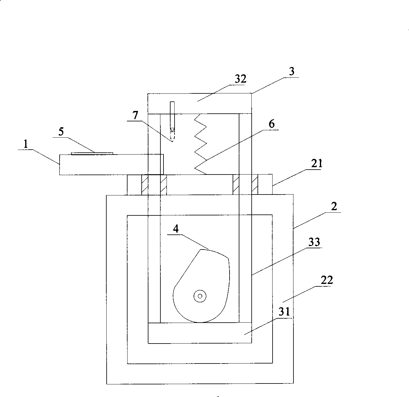
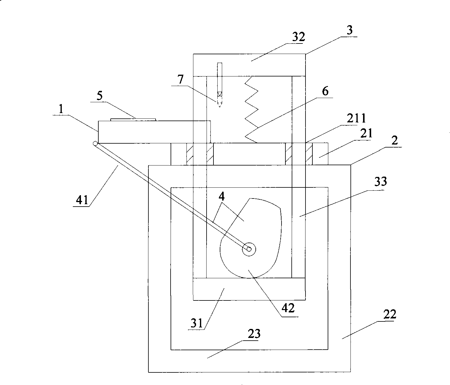
[0030] Such as image 3 Shown is the structural representation of the test fixture of the embodiment of the present invention, and described test fixture comprises:

[0031] The carrier plate 1 is arranged on a support 2 for placing the object to be tested 5;

[0032] The sliding part 3 is suspended on the support 2 supported by the elastic part 6, and the downward probe 7 is arranged on the sliding part 3;

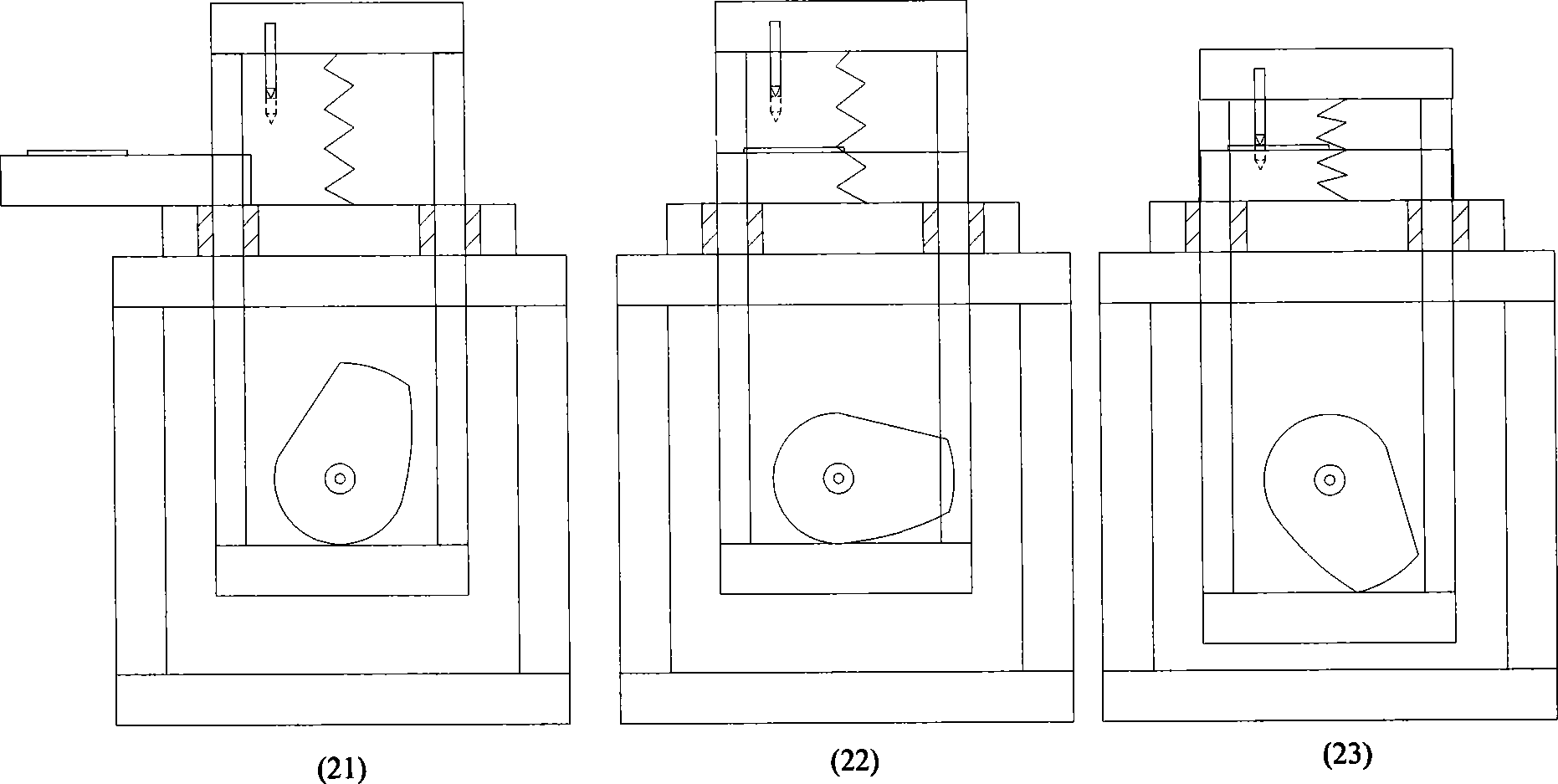
[0033] The rotating part 4 is fixed on the bracket 2 and includes a first rotating body 41 and a second rotating body 42. When the rotating part 4 rotates, the first rotating body 41 drives the carrier plate 1 to the The downward movement of the probe 7 drives the sliding part 3 down through the second rotating body 42 , and when the rotating part 4 rotates to a preset position, the probe 7 contact...


PUM


Abstract

The invention provides a test clamp and the test method. The test clamp comprises a carrier plate arranged on a support and used for placing the object to be tested; a sliding part which is suspended on the support by the supporting of an elastic part, wherein the sliding part is provided with a probe facing downwards, and a rotating part fixed on the support and comprising a first rotating body and a second rotating body, wherein, when the rotating part rotates, the first rotating body drives the carrier plate to move towards the lower part of the probe, and the second rotating body drives the sliding part to slide downwards, and when the rotating part rotates to a preset position, the probe contacts the object to be tested. By using the invention, the number of operating the clamp is reduced, and the production efficiency is improved.

Description

technical field [0001] The invention relates to the field of circuit board testing, in particular to a testing fixture and a testing method. Background technique [0002] In the production process of printed circuit board (PCB, Printed circuit board), a large number of layout, welding and other process steps are required. Therefore, testing and inspection are extremely important for producing high-quality printed circuit boards. [0003] Currently, special test fixtures are usually used to test the performance of printed circuit boards, such as figure 1 Shown is a schematic structural view of a test fixture in the prior art. The test fixture in the prior art includes: a carrier plate 1, a bracket 2, a sliding part 3 and a cam 4, and the carrier plate 1 is used to place a printed circuit to be tested Plate 5, the bracket 2 includes: a panel 21 and a side plate 22; the sliding part 3 is suspended on the bracket 2 through a spring 6, and the sliding part 3 includes: a base 31,...

Claims


Application Information

Patent Timeline
Patent Type & Authority Applications(China)
IPC IPC(8): G01R1/04G01R31/00
Inventor 冯正本
Owner SHENZHEN TRANSSION HLDG CO LTD
Why Eureka
Try Eureka