Circuit for controlling device switch and control method thereof

A technology for controlling equipment and controlling switches, which is applied in the direction of program control and electrical program control in sequence/logic controllers, which can solve problems such as large hardware investment, increased cost, and complicated wiring, and achieve hardware cost and installation cost savings. , the effect of reducing the amount of input

Inactive Publication Date: 2009-05-27
CHERY AUTOMOBILE CO LTD
View PDF0 Cites 0 Cited by
  • Summary
  • Abstract
  • Description
  • Claims
  • Application Information

AI Technical Summary

Problems solved by technology

Although the above-mentioned control circuit and control method are simple in design, there are the following problems: 1. The investment in hardware is large. Two sets of buttons require two processing unit input points, two sets of connections are required, and the number of spare parts required is large, resulting in increased cost; 2. The wiring is complex and the construction volume is large, resulting in an increase in installation costs

Method used


Image

  • Circuit for controlling device switch and control method thereof
  • Circuit for controlling device switch and control method thereof

Examples


Embodiment 1

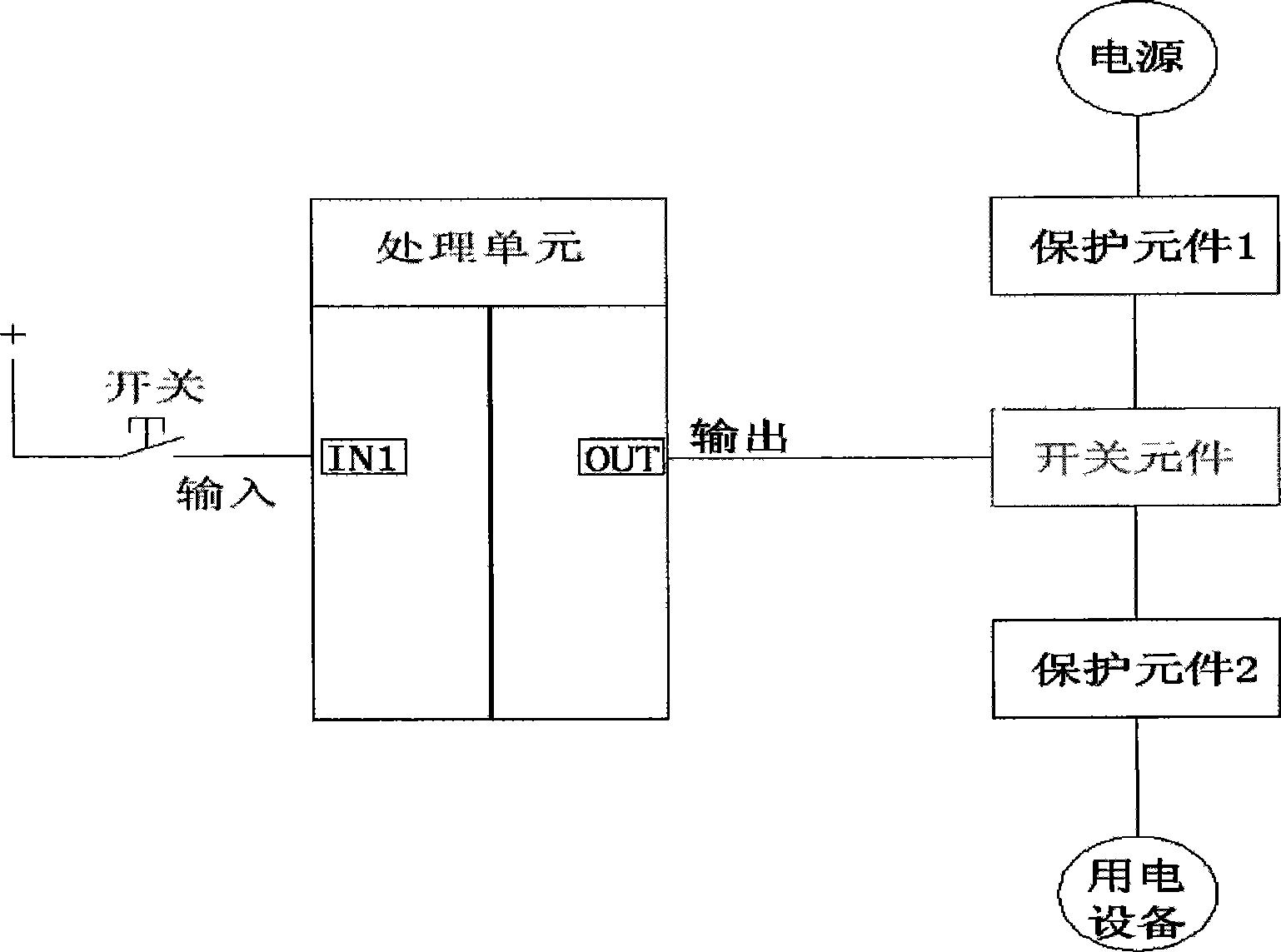
[0018] like figure 2 As shown, in the circuit for controlling the switch of the equipment in this embodiment, a set of equipment corresponds to only one control switch, the control switch is connected to the input terminal of the processing unit, and the signal of the control switch is processed by the processing unit and then output to the output terminal through the output terminal. The switch element of the corresponding electrical equipment controls the switch of the equipment. The processing unit is a PLC.

[0019] The control method of the above circuit is as follows: the processing unit receives the signal of the control switch, and when the processing unit detects the pulse signal of the control switch, the processing unit sends a control signal to change the switch state of the device. The control method can be realized by PLC programming. When the level of the input pin of the PLC changes, the PLC converts the level change into a pulse signal for processing.

Embodiment 2

[0021] Different from the above-mentioned Embodiment 1, the control method of this embodiment is as follows: the processing unit receives the signal of the control switch, when the processing unit detects the pulse signal of the control switch, the control unit changes the data value of its memory, and according to The changed data value of the memory outputs a control signal to change the switch state of the device.

[0022] For example: after the PLC is initialized, the data value of its memory is "0", and the switch state of the corresponding device is "off". When the PLC detects the pulse signal of the control switch, the PLC first changes the data value of its memory to "1" ”, and then send a control signal to turn on the device, so that the data value of the PLC memory corresponds to the switch state of the controlled device, that is, the data value of the memory “0” corresponds to the “off” state of the device, and “1” corresponds to the “off” state of the device. The "...


PUM


Abstract

The invention aims to provide an equipment on-off control circuit which has fewer elements and is low in cost, simple and practical and a control method thereof. The key points of the equipment on-off control circuit are that each set of equipment has a corresponding control switch which is connected with an input end of a processing unit and that a signal of the control switch is output to the corresponding equipment to control the switching of the equipment after being processed by the processing unit. The processing unit receives the signal from the control switch. When the electrical level of the control switch changes, the processing unit sends a control signal to change the on-off state of the equipment. The equipment on-off control circuit and the control method thereof save an input switch and an input module required by the prior circuit on the premise of realizing an equipment control function, use one switch to control the equipment, and reduce hardware investment, thereby reducing hardware cost and installation cost. The circuit and the method are particularly suitable for industries with extremely high requirements on cost and space such as automobile industry.

Description

technical field [0001] The present invention relates to a circuit for controlling a switch of a device and a control method thereof. Background technique [0002] like figure 1 As shown, in the general "start" and "stop" control circuit, the secondary control loop is usually used to control the equipment, that is, the control loop is formed by connecting the start button and the stop button with the processing unit. When the start or stop button is pressed, the button will send a signal to the processing unit to start or stop, and then the processing unit generates and outputs a control signal through the internally set program to control the contactor to be energized or de-energized, thereby turning on or off The power supply of the equipment to achieve the purpose of controlling the switch of the equipment. Although the above-mentioned control circuit and control method are simple in design, they have the following problems: 1. The hardware investment is large, two sets ...

Claims


Application Information

Patent Timeline
Patent Type & Authority Applications(China)
IPC IPC(8): G05B19/05
Inventor 赵明
Owner CHERY AUTOMOBILE CO LTD
Why Eureka
Try Eureka