Structure of touch control type apparatus and touch control type display panel

A display panel and touch technology, which is applied to the structure of touch devices and the field of touch display panels, and can solve problems such as high cost, heavy weight, and insufficient sensing signal strength

Active Publication Date: 2009-05-27
AU OPTRONICS CORP
View PDF0 Cites 48 Cited by
  • Summary
  • Abstract
  • Description
  • Claims
  • Application Information

AI Technical Summary

Problems solved by technology

Since the known touch display panel is manufactured separately from the touch panel and the liquid crystal display panel, and then the touch panel and the liquid crystal display panel are assembled together, the weight is heavy, the cost is high, and the light transmittance is low. Disadvantages, in order to solve the above shortcomings, recently developed a touch component and display component on the same panel to form a liquid crystal display panel with touch function
Generally, the touch

Method used


Image

  • Structure of touch control type apparatus and touch control type display panel
  • Structure of touch control type apparatus and touch control type display panel
  • Structure of touch control type apparatus and touch control type display panel

Examples


Embodiment Construction

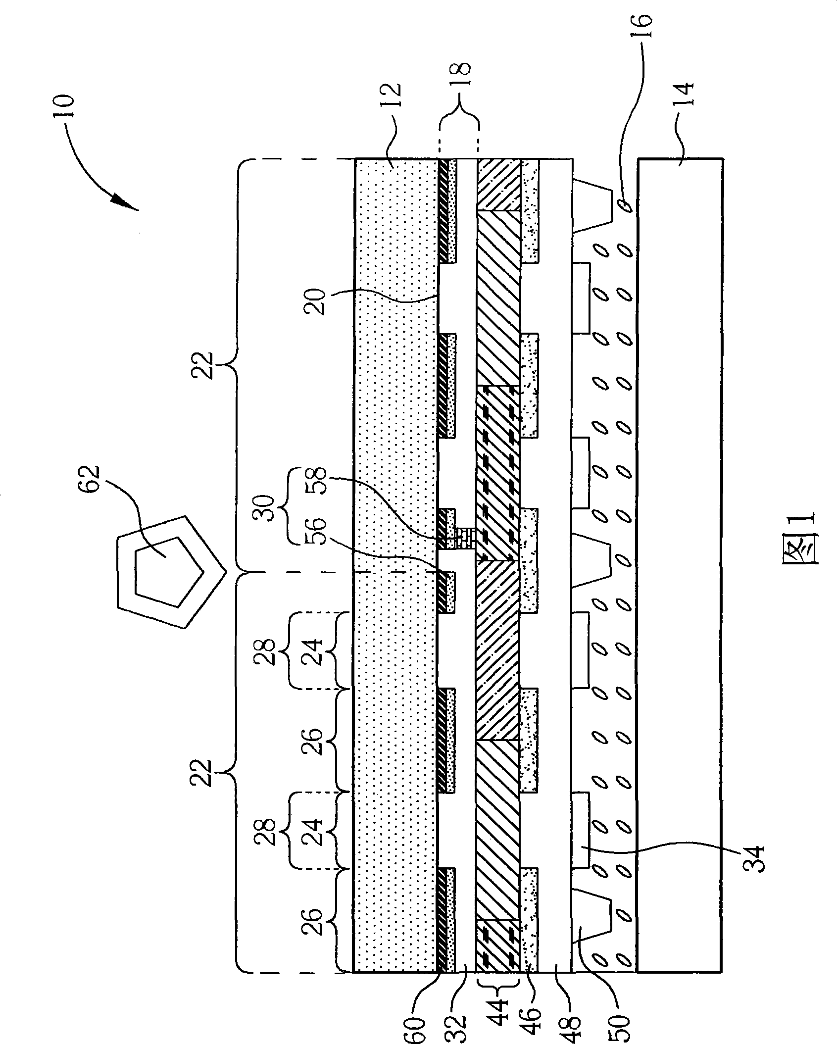
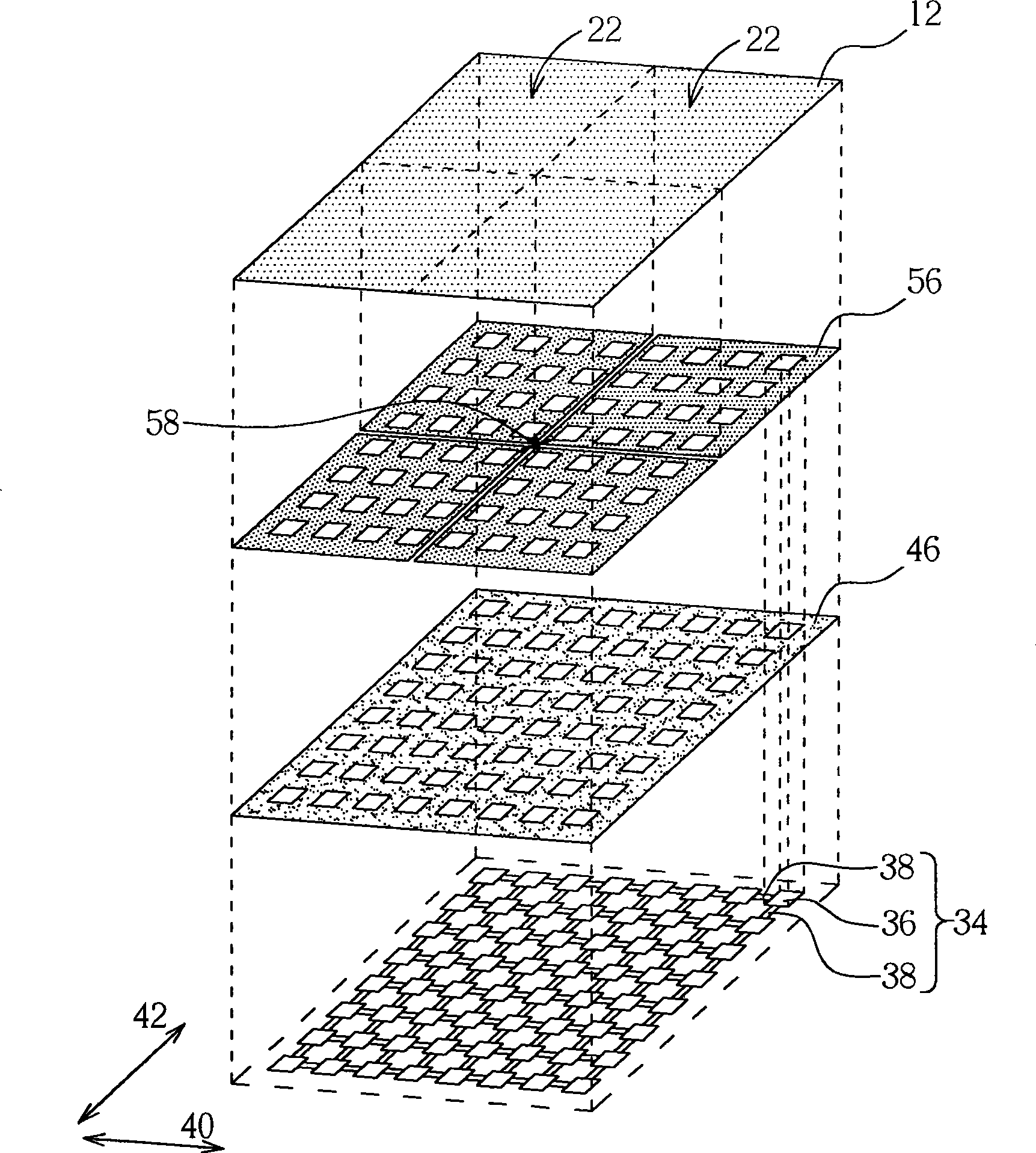
[0035] Please refer to Figure 1 with figure 2 , FIG. 1 is a schematic cross-sectional structure diagram of a touch display panel according to a first preferred embodiment of the present invention, figure 2 It is a schematic structural diagram of the touch display panel according to the first preferred embodiment of the present invention. As shown in Figure 1 with figure 2 As shown, the touch display panel 10 includes a first substrate 12 , a second substrate 14 , a liquid crystal layer 16 and a touch device structure 18 . The first substrate 12 and the second substrate 14 are parallel to each other, the first substrate 12 has a substrate surface 20 opposite to the second substrate 14, and the substrate surface 20 defines a plurality of sensing regions 22, and each sensing region 22 defines a A plurality of display areas 24 arranged in an array and light-shielding areas 26 between the display areas 24, wherein the first substrate 12 can be a transparent substrate such as a gl...


PUM


Abstract

The invention discloses a structure for a touch control device and a touch control display panel. The touch control device comprises a patterned sensing electrode structure, an insulating layer and a patterned sharing electrode layer. The patterned sensing electrode structure is arranged on the surface of a substrate defined with a plurality of display areas and a shading area, wherein the display areas are exposed corresponding to the shading area. The insulating layer covers the patterned sensing electrode structure. The patterned sharing electrode layer is arranged on the surface of the insulating layer, and comprises a plurality of electrode parts corresponding to the display areas and a plurality of connecting parts arranged between adjacent electrode parts and electrically connected to the electrode parts. The touch control device provides the patterned sensing electrode structure corresponding to the shade area, coordinately provides the electrode parts of the patterned sharing electrode layer corresponding to the display areas, and reduces area of the connecting parts to reduce superposition area of the patterned sensing electrode structure and the patterned sharing electrode layer, so as to reduce coupling capacitance thereof and promote intensity of sensed signals sensed by the patterned sensing electrode structure.

Description

technical field [0001] The invention relates to a structure of a touch device and a touch display panel. Background technique [0002] A liquid crystal display (LCD) is currently the most widely used type of flat panel display, which has the characteristics of power saving, thin shape and light weight. In various electronic devices including liquid crystal displays, such as electronic devices such as multimedia players, mobile phones or personal digital assistants (PDAs), the function of using liquid crystal displays to perform touch input has gradually become popular, that is, touch panel application is becoming more and more widespread. [0003] Traditional touch display panels are mainly resistive touch display panels and capacitive touch display panels. Resistive touch display panels use voltage drop to locate the touch position, and capacitive touch display panels usually include sensing capacitors. According to The touch position is located through signal processing ...

Claims


Application Information

Patent Timeline
IPC IPC(8): G06F3/041G02F1/133
Inventor 杨敦钧李锡烈黄伟明
Owner AU OPTRONICS CORP
Why Eureka
Try Eureka