Light emitting diode combination

A technology of light-emitting diodes and light-emitting chips, which is applied in optics, condenser mirrors, optical components, etc., can solve the problems of low utilization rate of light energy of light-emitting diodes and affect the overall brightness of light-emitting diode lamps, and achieve the goal of avoiding loss of light intensity and high intensity Effect

Inactive Publication Date: 2009-05-27
FU ZHUN PRECISION IND SHENZHEN +1
View PDF0 Cites 6 Cited by
  • Summary
  • Abstract
  • Description
  • Claims
  • Application Information

AI Technical Summary

Problems solved by technology

As a result, part of the light emitted by the chip cannot pass through the air between the cladding layer and the lens to reach the lens due to its too large incident angle, resulting in low light energy utilization efficiency of the LED and affecting the overall brightness of the LED lamp

Method used


Image

  • Light emitting diode combination
  • Light emitting diode combination
  • Light emitting diode combination

Examples


Embodiment Construction

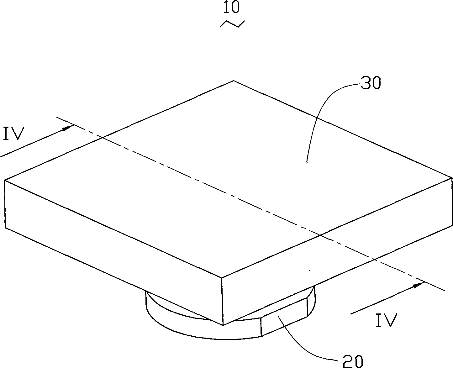
[0017] Such as figure 1 As shown, the LED combination 10 of the present invention includes a LED 20 and a lens 30 fixed on the LED 20 .

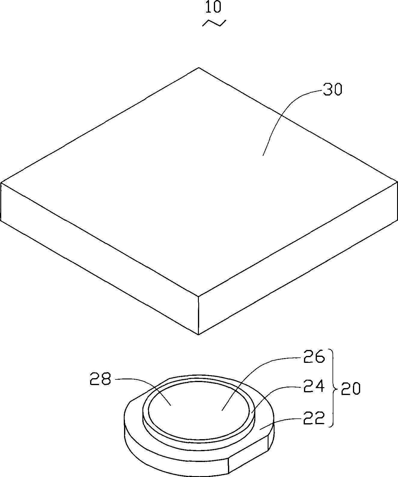
[0018] see figure 2 with Figure 4 The light-emitting diode 20 includes a base 22, a light-emitting chip 220 bonded on the base 22, a side wall 24 extending vertically upward from the base 22, and a package accommodated in the side wall 24 and covering the chip 220. Cladding 26. The base 22 is roughly circular, and two opposite sides of the base 22 are respectively cut off to form two parallel sides. The chip 220 is bonded to the central area of ​​the upper surface of the substrate 22 by a die-bonding glue (not shown). According to different structures of the chip 220 , the die-bonding adhesive can be an insulating die-bonding adhesive, such as relatively pure epoxy resin, or a conductive die-bonding adhesive, such as epoxy resin doped with silver paste. The sidewall 24 is ring-shaped, and is formed on the upper surface of the base 22 ...


PUM


Abstract

The invention discloses an LED combination. The combination comprises an LED and a lens, wherein the LED comprises an LED chip and a clad which is used to cover the LED chip; and the lens is attached to the clad directly or connected with the clad through gel, so that the light beams which the chip gives out are transmitted to outside through the clad and the lens directly. Compared with the prior art, the combination has the advantages that the clad of the LED is attached to the lens directly or connected with the lens through the gel, and no air between the clad and the lens, so the light beams which the chip gives out can pass through the clad directly and reach the lens; and the combination prevents losing light intensity between the clad and the lens caused by perfect reflection of the light beams. Therefore, the light beams transmitted to outside can obtain higher intensity.

Description

technical field [0001] The invention relates to a combination of light emitting diodes, in particular to a combination of light emitting diodes with high luminous intensity. Background technique [0002] Compared with traditional light-emitting sources, light-emitting diodes have the advantages of light weight, small size, low pollution, long life, and high photoelectric conversion efficiency. As a new type of light-emitting source, they have been increasingly used in various fields . All current light-emitting diodes include a light-emitting chip and a cladding layer wrapping the chip. This coating is used to protect the chip from the external environment. When the chip is powered on, it radiates light through the electroluminescent effect. [0003] Most of the current LED lamps use a combination of LEDs, reflectors and lenses. The reflector surrounds the LEDs and reflects the light emitted from the side of the LED's cladding to and from the LED's cladding. The light em...

Claims


Application Information

Patent Timeline
Patent Type & Authority Applications(China)
IPC IPC(8): H01L33/00H01L33/58
CPCH01L33/58G02B19/0061G02B19/0028G02B17/0868
Inventor 徐方伟余光赖振田
Owner FU ZHUN PRECISION IND SHENZHEN
Why Eureka
Try Eureka