Motor equipped with reducer and method of manufacturing the same

A technology with a reducer and a reducer, applied in the direction of controlling mechanical energy, electrical components, electromechanical devices, etc., can solve the problems of reduced coaxial performance and complicated connecting shafts, and achieve the effect of improving meshing accuracy

Active Publication Date: 2009-05-27
MABUCHI MOTOR
View PDF3 Cites 22 Cited by
  • Summary
  • Abstract
  • Description
  • Claims
  • Application Information

AI Technical Summary

Problems solved by technology

However, such a connecting shaft is obviously a complex structure, and the coaxial performance is reduced

Method used


Image

  • Motor equipped with reducer and method of manufacturing the same
  • Motor equipped with reducer and method of manufacturing the same
  • Motor equipped with reducer and method of manufacturing the same

Examples


no. 1 Embodiment approach

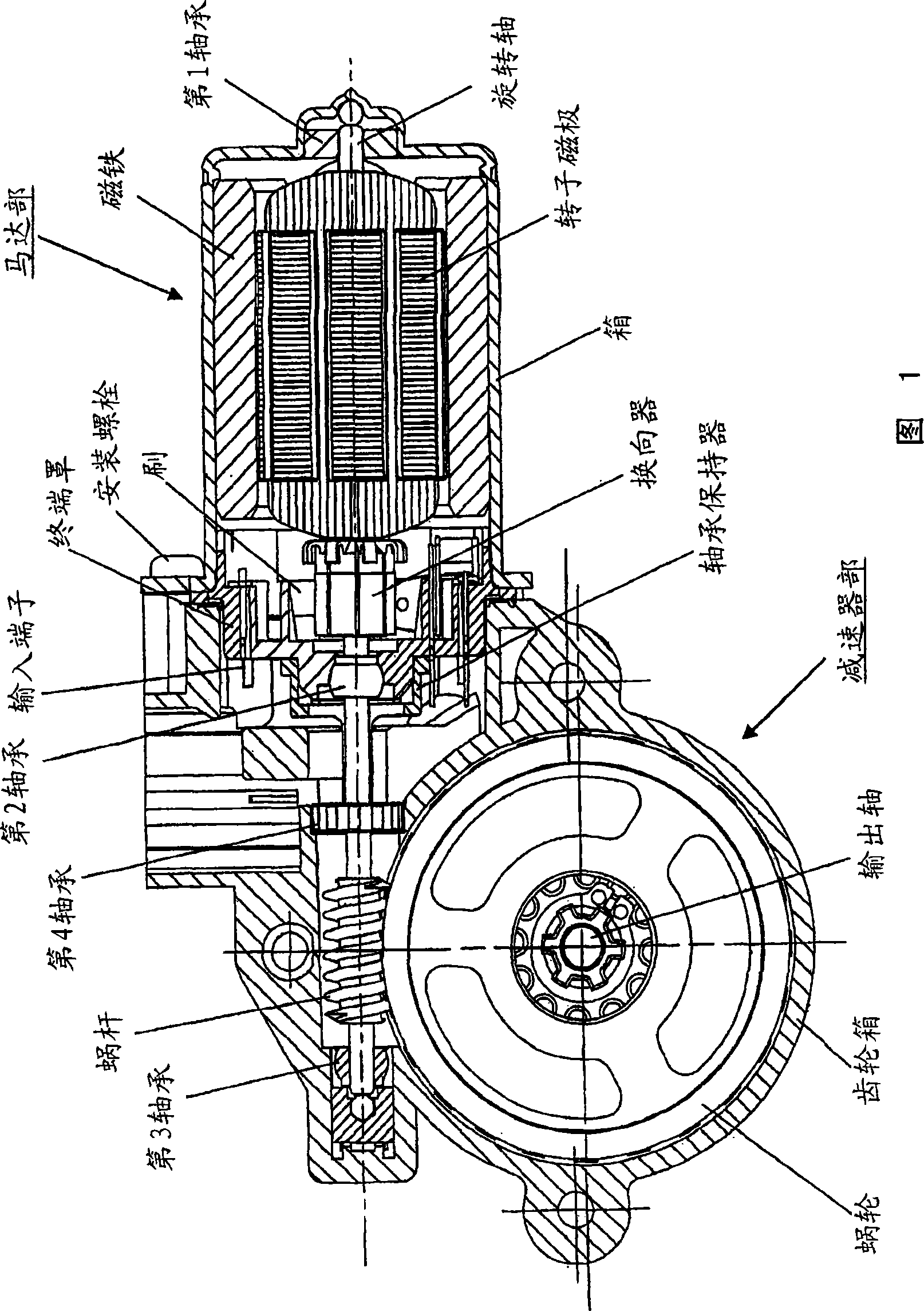
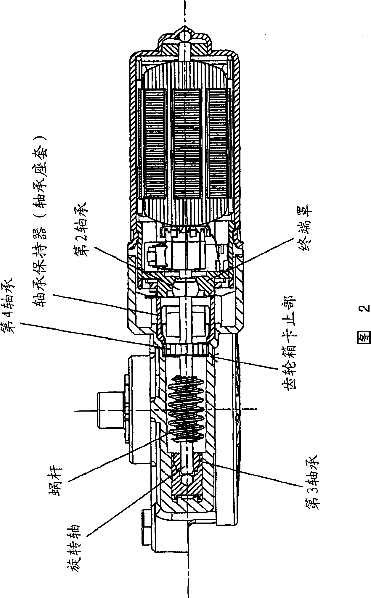
[0036] Fig. 2 is a cross-sectional view viewed from above in Fig. 1 , showing a fourth bearing and its vicinity, which is a feature of the present invention. As shown in the figure, the fourth bearing for supporting the rotating shaft is installed in the gearbox between the second bearing and the worm housed in the center of the end cover.

[0037] In the first embodiment, the fourth bearing is fixed by using the bearing sleeve as a bearing holder. After the fourth bearing is inserted into the rotating shaft, it is sandwiched and fixed between the locking portion of the gear case and the bearing sleeve from both sides. The locking portion of the gear case may be formed by a step or a protrusion integrally formed on the resin gear case.

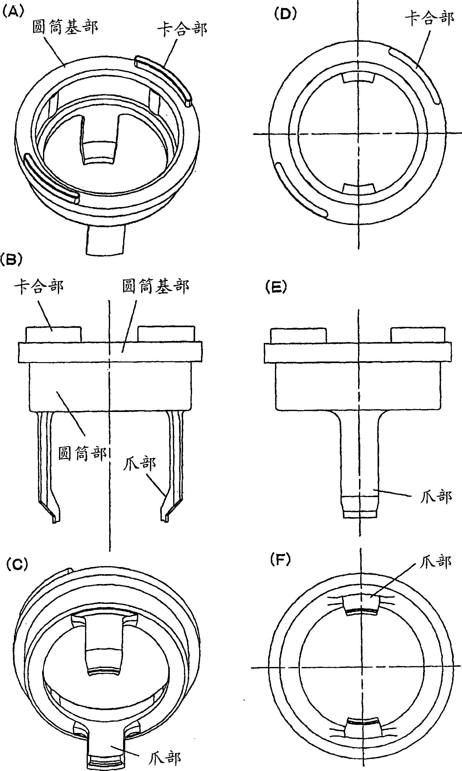
[0038] image 3is a diagram showing the bearing housing supporting the 4th bearing alone, image 3 (A)~ image 3 (F) is a figure which changed only the viewing direction of the same bearing sleeve. As shown in the figure, the bearing hous...

no. 2 Embodiment approach

[0046] In the second embodiment, the fourth bearing is fixed using the terminal holder as the bearing holder. Figure 7 It is a figure explaining the terminal holder. Figure 7 (A) is a view viewed from the outside (front side) of the motor unit, Figure 7 (B) is a figure seen from the inside (back side) of a motor part. Like the bearing housing of the first embodiment, this terminal holder not only has the function of supporting the fourth bearing, but also has a conductive member that guides the motor input terminal to a position suitable for connecting to an external lead, and can be installed with an electrical composed of components. Electrical components such as choke coils and capacitors for the purpose of noise cancellation can be mounted on this terminal holder.

[0047] On the front side of the terminal holder integrally formed of resin, the two claws integrally formed with resin on the left and right sides of the center hole for fitting the bearing holding part a...


PUM


Abstract

A motor equipped with a reducer includes a motor section, and a reducer section assembled to the motor section. The motor section has a first bearing provided at the center of a bottom portion of a closed-bottomed tubular casing, a second bearing provided at the center of an end bell fitted to an opening portion of the casing, and a rotating shaft which is supported by the first bearing and the second bearing and extends outward from the motor section in such a manner that a distal end of the rotating shaft is rotatably supported by a third bearing provided within the reducer section. The motor equipped with a reducer further includes a fourth bearing adapted to support the rotating shaft and provided within the reducer section, and a bearing holder for fixedly holding the fourth bearing between the bearing holder and a stopper portion provided on the gear box.

Description

technical field [0001] The present invention relates to, for example, a motor with a speed reducer that can be used for opening and closing a window glass of an automobile and a manufacturing method thereof. Background technique [0002] Figure 13 It is a longitudinal sectional view of a conventional motor with a reducer (see Patent Document 1). This motor with a reducer is integrally assembled with a motor part and a reducer part. In the speed reducer unit, a worm connected to a rotating shaft, a worm wheel meshed with it, and the like are housed in the gear case. [0003] The bearings that support the rotating part of the motor unit require two locations, a first bearing and a second bearing, on the motor side, and a total of three bearings, a third bearing, on the gearbox side. Among them, the second bearing located in the center is accommodated in the end cover of the motor part, and the end cover is held in a form sandwiched between the motor part and the speed reduc...

Claims


Application Information

Patent Timeline
Patent Type & Authority Applications(China)
IPC IPC(8): H02K7/116
CPCH02K7/081H02K11/0021H02K7/1166H02K11/215Y10T29/49009Y10T74/19684
Inventor 佐谷务小岛正寿
Owner MABUCHI MOTOR
Why Eureka
Try Eureka