Annular pin

A pin and ring technology, which is applied in the direction of fasteners, connecting components, fixed labels, etc., can solve problems such as the breaking strength of the difficult-to-clip connection part, damage to the locking tab, and reduced efficiency

Inactive Publication Date: 2004-04-21
KOTECS +1
View PDF0 Cites 2 Cited by
  • Summary
  • Abstract
  • Description
  • Claims
  • Application Information

AI Technical Summary

Problems solved by technology

[0013] Therefore, when the unit length L of the clip assembly is limited, the number of clips arranged on the clip assembly per unit length has to be reduced, which greatly reduces the efficiency of making such clips into commercial products.
[0014] On the other hand, if the interval formed between the clips is shortened, the thickness of the threading loop portion must be reduced, so that it is difficult to obtain the desired breaking strength of the clip connection portion.
[0015] Additionally, if Figure 18 As shown, when inserting the head portion 5 into the insertion hole 6b of the threading ring portion 6, due to the swing of

Method used


Image

  • Annular pin
  • Annular pin
  • Annular pin

Examples


Embodiment Construction

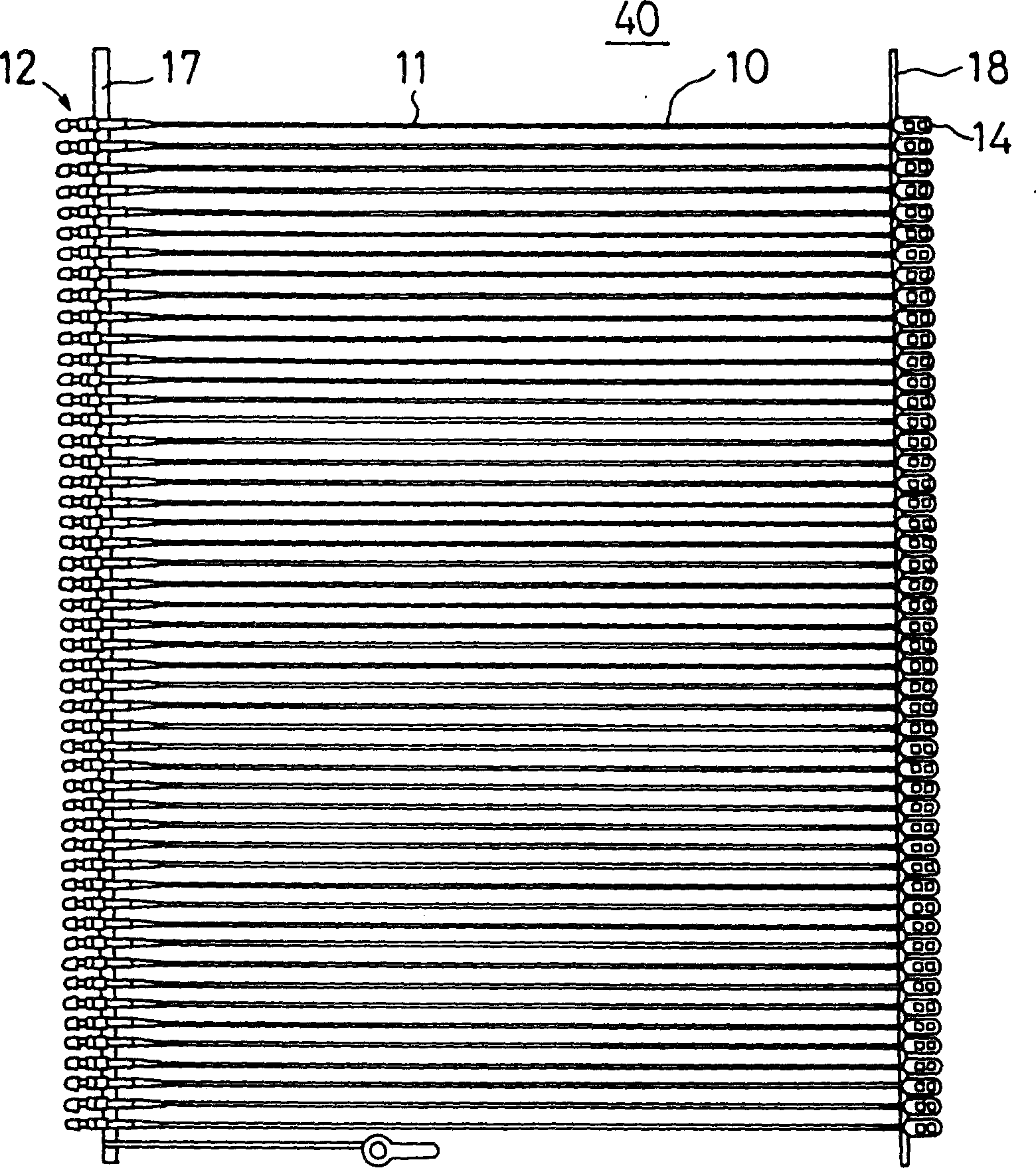
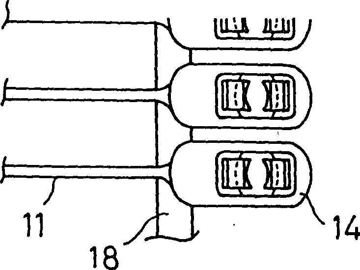
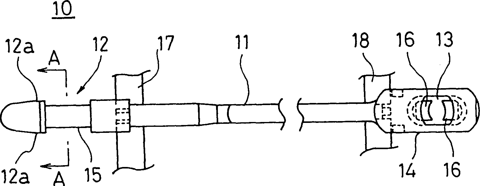
[0046] In order to overcome the problems of the prior art, the present invention provides a clip in a clip assembly having a plurality of clips, each clip comprising a flexible thread; , and has a suitable matching part; it also includes a threading ring part, which is set at the other end of the thin wire, and has an embedded hole, which can make the embedded head part pass through in one direction. said thread, insert portion and threading ring portion are integrally arranged in a manner parallel to each other across the connecting strip to allow a portion of each clip to be detachably attached thereto; said loop clips are constructed such that the insert The part and the threading ring part can be connected to each other between the fitting part and the stepped part, the fitting part is formed on the edge part of the socket part and provided near the connection part formed between the socket part and the thin wire, the The stepped portion is provided in the through hole for...


PUM

PropertyMeasurementUnit
Major axis diameteraaaaaaaaaa

Abstract

A loop pin with high tensile rupture strength has an insertion head portion with an appropriate mating part on one end of the filament and a socket portion comprising a hole for irreversibly passing the insertion head portion provided on the other end of the filament, wherein one part of the insertion head portion has formed on it two parallel surfaces along the axial direction thereof.

Description

technical field [0001] This invention relates to clips mounted on labels such as brand marks, price tags, material description labels, etc., or on product instruction labels such as clothing, shoes or bags, and more particularly to a clip assembly in which a plurality of such clips are arranged in close proximity to each other in parallel so that each clip is detachably attached to the connecting strip and each clip is detached from said assembly one by one by means of a specially designed rivet gun or similar device, so that each clip can be used. Background technique [0002] Various types of clips have been used in the past to fasten and attach products such as clothing, sundries, sandals and shoes, such as brand indicia or price tags. [0003] For example, such a clip 1 has a thin thread 7 which passes through a label to form a loop, an inset portion 5 at one end thereof, and a threading loop portion 6 at the other end thereof, which There is a hole 6a through which sa...

Claims


Application Information

Patent Timeline
IPC IPC(8): B65C7/00A44B99/00G09F3/14
CPCG09F3/14Y10T24/153Y10T24/14Y10T24/141Y10T24/1498Y10T292/499Y10T292/495A44B99/00
Inventor 上野英幸
Owner KOTECS
Why Eureka
Try Eureka