Special assembling machine for large screw-type rotor

A screw type and rotor technology, which is applied in the field of assembly of large screw type rotors, can solve problems such as inconvenient operation, potential safety hazards, damaged bearing bushes, etc., and achieves good stability, no collision, and reduced assembly damage.

Pending Publication Date: 2021-08-13
青岛欧开智能系统有限公司
View PDF0 Cites 2 Cited by
  • Summary
  • Abstract
  • Description
  • Claims
  • Application Information

AI Technical Summary

Problems solved by technology

However, since both the male rotor 13 and the female rotor 14 are heavy in weight, there are inconvenient operations and potential safety hazards during the hoisting process. At the same time, workers are required to continuously adjust the rotor angle during the meshing assembly process, which is inefficient and has large errors.
In addition, the coating on the surface of the bearing bush of the exhaust end seat 1 can form an oil film with the rotor, which can effectively protect the rotor. However, due to the low hardness of the coating, a slight collision can cause damage, and protection is required; while the manual hoisting rotor penetrates During the process of the exhaust end seat 1 bearing bush, due to hoisting shaking, rotor inertia, etc., it is difficult to ensure that the rotor does not collide with the bearing bush, damage the bearing bush, and affect the operation effect of the compressor

Method used


Image

  • Special assembling machine for large screw-type rotor
  • Special assembling machine for large screw-type rotor
  • Special assembling machine for large screw-type rotor

Examples


Embodiment 1

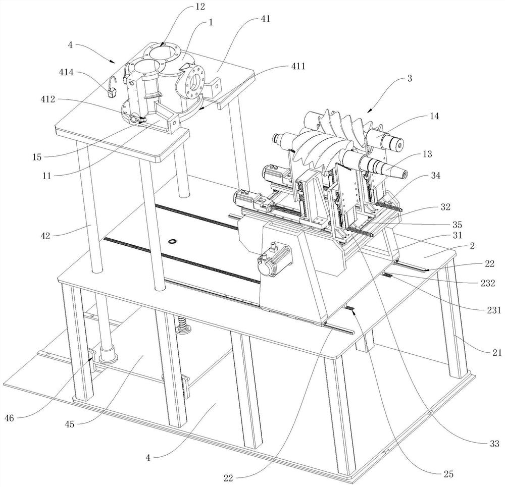
[0047] refer to figure 2 and image 3 , which is a special assembly machine for a large-scale screw rotor disclosed in the present invention, includes a cuboid-shaped bearing plate 2, four legs 21 are fixedly connected to the lower side of the bearing plate 2, and the four legs 21 are respectively located on the bearing plate 2 at the four sharp corners; the upper side of the bearing plate 21 is provided with a two-rotor automatic meshing device 3, an exhaust end seat bearing device 4, and a special machine data processing center, and the two rotor automatic meshing devices 3 can tend to approach along the length direction of the carrier plate 2 The exhaust end seat carrying device moves in 4 directions.

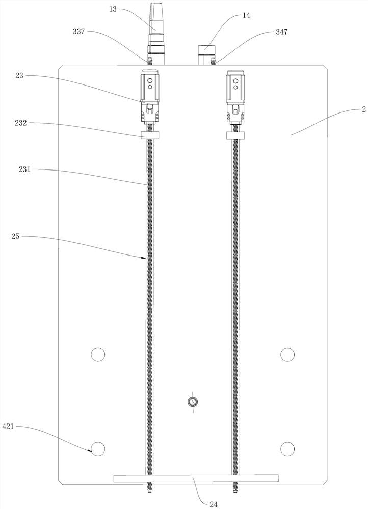
[0048] The supporting plate 2 is provided with a first guiding mechanism 22 for guiding the two rotor automatic meshing devices 3 towards the direction of the exhaust end seat supporting device 4. The number of the first guiding mechanisms 22 is two groups and the first tw...

Embodiment 2

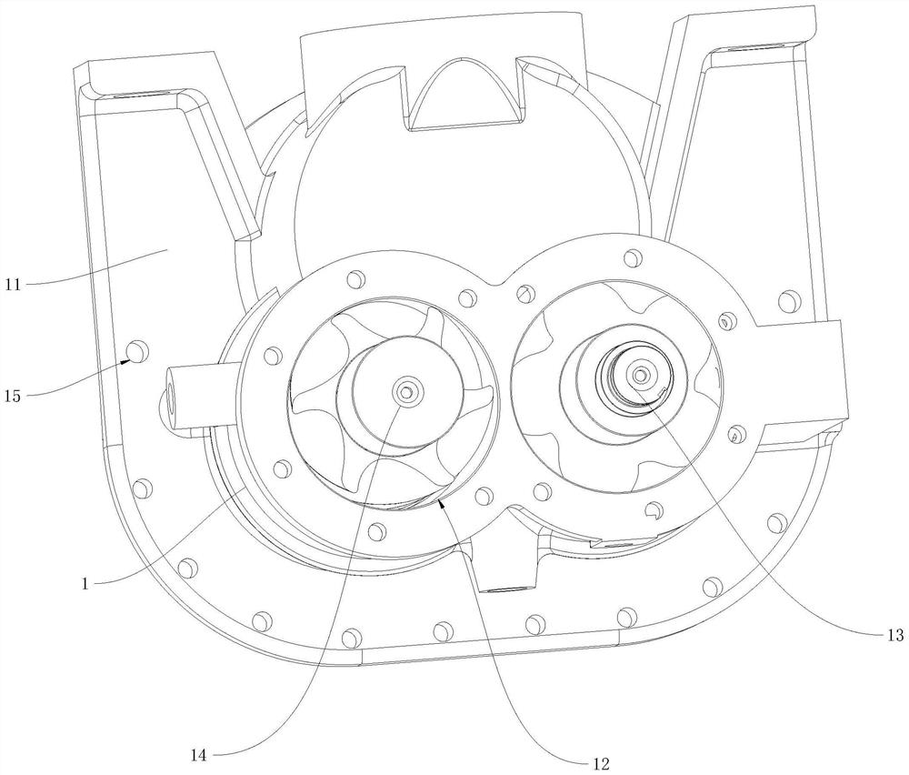
[0066] The difference between this embodiment and Embodiment 1 is that in this embodiment, refer to Figure 10 to Figure 13 , the lifting plate 41 is vertically arranged, and the side of the lifting plate 41 close to the automatic meshing device 3 of the two rotors is provided with a through groove 411, the axis of the through groove 411 is arranged horizontally and the through groove 411 runs through the lifting plate 41 along its axis direction, so as to be able to carry The exhaust end seat 1 and the male rotor 13 and the female rotor 14 are respectively inserted into the slots 12 corresponding to the exhaust end seat 1 through the through groove 411; the through groove 411 extends upward to the upper end of the lifting plate 41 to form an opening, It is convenient for the exhaust end seat 1 to be placed in the through groove 411 . There is also a horizontal supporting plate 416 fixedly connected to the bottom of the middle part of the lifting plate 41 corresponding to the ...


PUM


Abstract

The invention relates to the technical field of screw compressors, in particular to a special assembling machine for a large screw-type rotor. According to the technical scheme, the special assembling machine comprises a bearing plate, the lower side of the bearing plate is fixedly connected with supporting legs, a two-rotor automatic meshing device, an exhaust end base bearing device and a special machine data processing center are arranged on the upper side of the bearing plate, and the two-rotor automatic meshing device can move in the direction close to the exhaust end base bearing device so that assembling of two rotors and an exhaust end base can be conveniently completed; the exhaust end base bearing device comprises a lifting plate which ascends and descends in the vertical direction, and a positioning piece for positioning the exhaust end base on the lifting plate is arranged on the lifting plate; and the lifting plate is further provided with two machine vision cameras which are respectively used for scanning and shooting the end surfaces of the two rotors, collecting information and transmitting data to the special machine data processing center. The special assembling machine has the advantages that the accuracy in an assembling process of the two rotors is improved, and the assembling efficiency is improved.

Description

technical field [0001] The invention relates to the technical field of screw compressors, in particular to a special machine for assembling large screw rotors. Background technique [0002] Screw compressors, also known as screw compressors, are widely used in refrigeration devices such as refrigeration, refrigeration, air conditioning, and chemical processes due to their simple structure, few wearing parts, and good air volume adjustment. The screw compressor cylinder is equipped with a pair of parallel and intermeshed screw type male rotor and female rotor. Both rotors have several concave teeth, and the concave teeth of the two rotors rotate in opposite directions. The gap between the two rotors and between the casing and the rotor is only 5 to 10 wires. The main rotor (also known as male rotor or convex rotor) is driven by an engine or an electric motor (mostly driven by an electric motor), and the other rotor (also known as a male rotor) is driven by an electric motor. ...

Claims


Application Information

Patent Timeline
Patent Type & Authority Applications(China)
IPC IPC(8): B23P21/00
CPCB23P21/00
Inventor 张晓兰张智超薛守智韩琳王斌
Owner 青岛欧开智能系统有限公司
Why Eureka
Try Eureka