Detachable locking rod

A split-type, stable rod technology, applied in the direction of fixator, internal fixator, internal bone synthesis, etc., can solve the problems of inability to change the spacing and the angle of the screw, up and down sliding, inconvenience, etc., to achieve easy revision and change, prevent The effect of sliding up and down for easy installation

Inactive Publication Date: 2011-01-12
丁真奇
View PDF0 Cites 0 Cited by
  • Summary
  • Abstract
  • Description
  • Claims
  • Application Information

AI Technical Summary

Problems solved by technology

This system has the following defects: 1. The distance between the two vertebral body screws of the same vertebral body and the screw-in angle cannot be changed
2. The width of the connecting plate is relatively fixed, and it is difficult to adapt to the situation where the width of some vertebral bodies is too small or too large
3. The connecting plate is designed as a straight plate; in case of certain rigid scoliosis and uneven surface of the vertebral body, it cannot be completely compliant during the operation
4. It is necessary to prepare connecting plates of different lengths to meet the specific needs of the operation, which is inconvenient
[0004] The nail-rod system is to install a vertebral body screw at both ends of the connecting rod. The disadvantages are: 1. The same gasket system is used on the same vertebral body, and the two screws pass through the fixed position on the gasket. hole, there is also the defect that the vertebral screw is difficult to divert
2. A cutting system with connecting rods is required for intraoperative cutting
3. There is no convenient top nail locking system, and there is a possibility of sliding up and down

Method used


Image

  • Detachable locking rod
  • Detachable locking rod
  • Detachable locking rod

Examples


Embodiment Construction

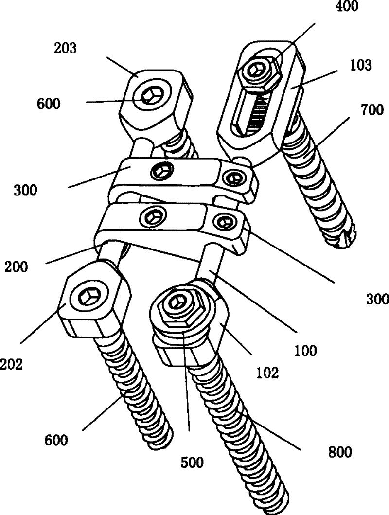
[0026] figure 1 The three-dimensional structure of an embodiment of the split locking rod of the present invention is shown. The split-type locking rod combines the strengths of the nail rod and nail-board system. The main body of the structure adopts a double nail rod structure, with a main support rod 100 and a stabilizing rod 200; and two transverse connections are arranged between the two rods 100 and 200 device 300.

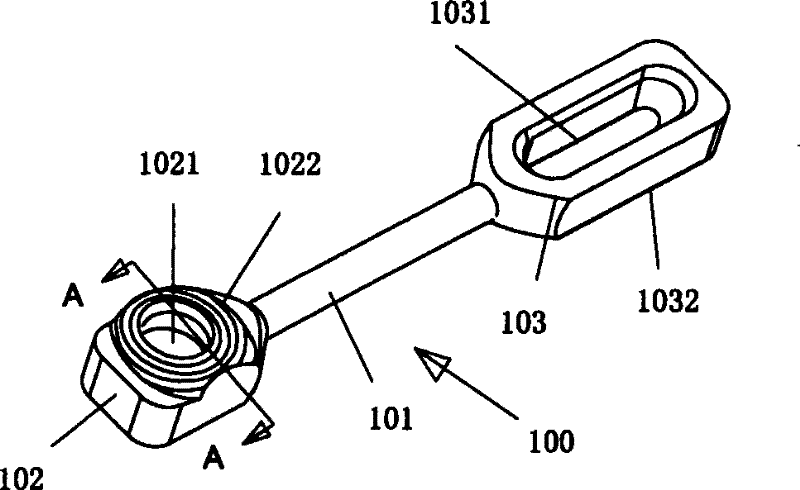
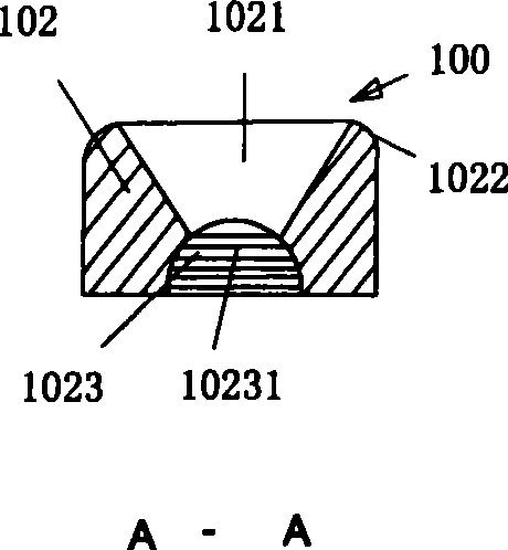
[0027] Please see diagram 2-1 , the middle section of the main support rod 100 is a round rod 101, there is a plate-shaped palm 102 at the proximal end, and a plate-shaped palm 103 at the far end. A through hole 1021 is provided on the palm portion 102 at the proximal end of the main support rod 100 . Please see Figure 2-2 The through hole 1021 of the palm portion 102 at the proximal end of the main support rod 100 has a conical hole section with the big end outside and a hemispherical hole section 1023 with the big end outside. The palm portion 102 a...


PUM


Abstract

The invention relates to a detachable locking rod, in particular to a thorax and lumbar spine reconstruction front path internal fixing device which is provided with a main supporting rod and a stabilizing rod, and the two ends of the main supporting rod and the stabilizing rod are respectively provided with a plate-shaped palm part; a hole is arranged at the palm part at the near-end of the mainsupporting rod and is internally provided with a centrum bolt; a sliding groove is arranged at the palm part at the remote-end of the main supporting rod and is internally provided with a centrum bolt; the palm parts at the two ends of the stabilizing rod are respectively provided with a screw hole which is internally screwed and joint with one centrum bolt; at least one transverse connecting device used for locking the mutual alignment of the main supporting rod and the stabilizing rod is arranged between the main supporting rod and the stabilizing rod; two ends of the transverse connecting device are respectively provided with a hook part which is used to block and connect with the corresponding rod, and each hook part is provided with a top thread locking the corresponding rod on the hook part. The invention solves the problem that the centrum bolts in a nail bat system and in a nail plate system are hard to rechannel. The operation is simple, and the fixation is reliable.

Description

technical field [0001] The invention relates to a split-type internal fixation device used for anterior surgery of human thoracolumbar spine. Background technique [0002] In the past, spinal thoracolumbar fractures, spinal tumors, tuberculosis and other spinal injuries after war trauma often used an anterior approach for spinal lesion resection and reconstruction after resection. The existing anterior internal fixation materials are mainly divided into two systems: nail plate and nail rod. But both systems have certain deficiencies. [0003] The nail-plate system is to set multiple vertebral body screws at both ends of the connecting plate. This system has the following defects: 1. The distance between two vertebral body screws of the same vertebral body and the angle of screw insertion cannot be changed. If the fixation angle of one of the vertebral screws is not ideal, it is difficult to achieve another diversion, that is, to reselect the screw fixation track. In addi...

Claims


Application Information

Patent Timeline
Patent Type & Authority Patents(China)
IPC IPC(8): A61B17/70
Inventor 丁真奇
Owner 丁真奇
Why Eureka
Try Eureka