Check patentability & draft patents in minutes with Patsnap Eureka AI!

Multiple yarn interlacing device

A yarn and component technology, applied in the field of interweaving devices for multi-yarns, can solve the problems of large number of components and keep them at a distance, and achieve the effect of fewer components and narrower distance between yarn paths

Inactive Publication Date: 2009-06-03
TMT MACHINERY INC
View PDF1 Cites 7 Cited by
  • Summary
  • Abstract
  • Description
  • Claims
  • Application Information

AI Technical Summary

Problems solved by technology

[0003] However, in the structure of the above-mentioned Patent Document 1, it is necessary to increase the number of yarn path members according to the number of yarns to be treated with the fluid, and the number of parts is large, so there is a tendency to stay away from it on site.

Method used


Image

  • Multiple yarn interlacing device
  • Multiple yarn interlacing device
  • Multiple yarn interlacing device

Examples


Embodiment Construction

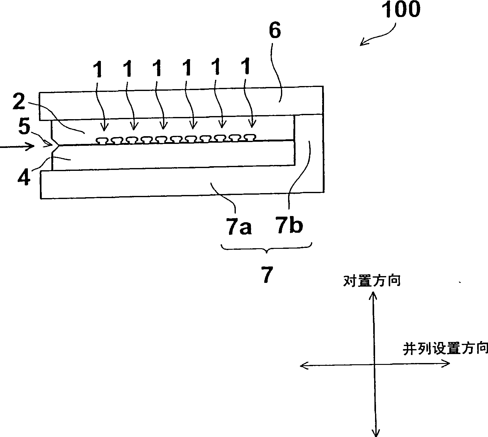
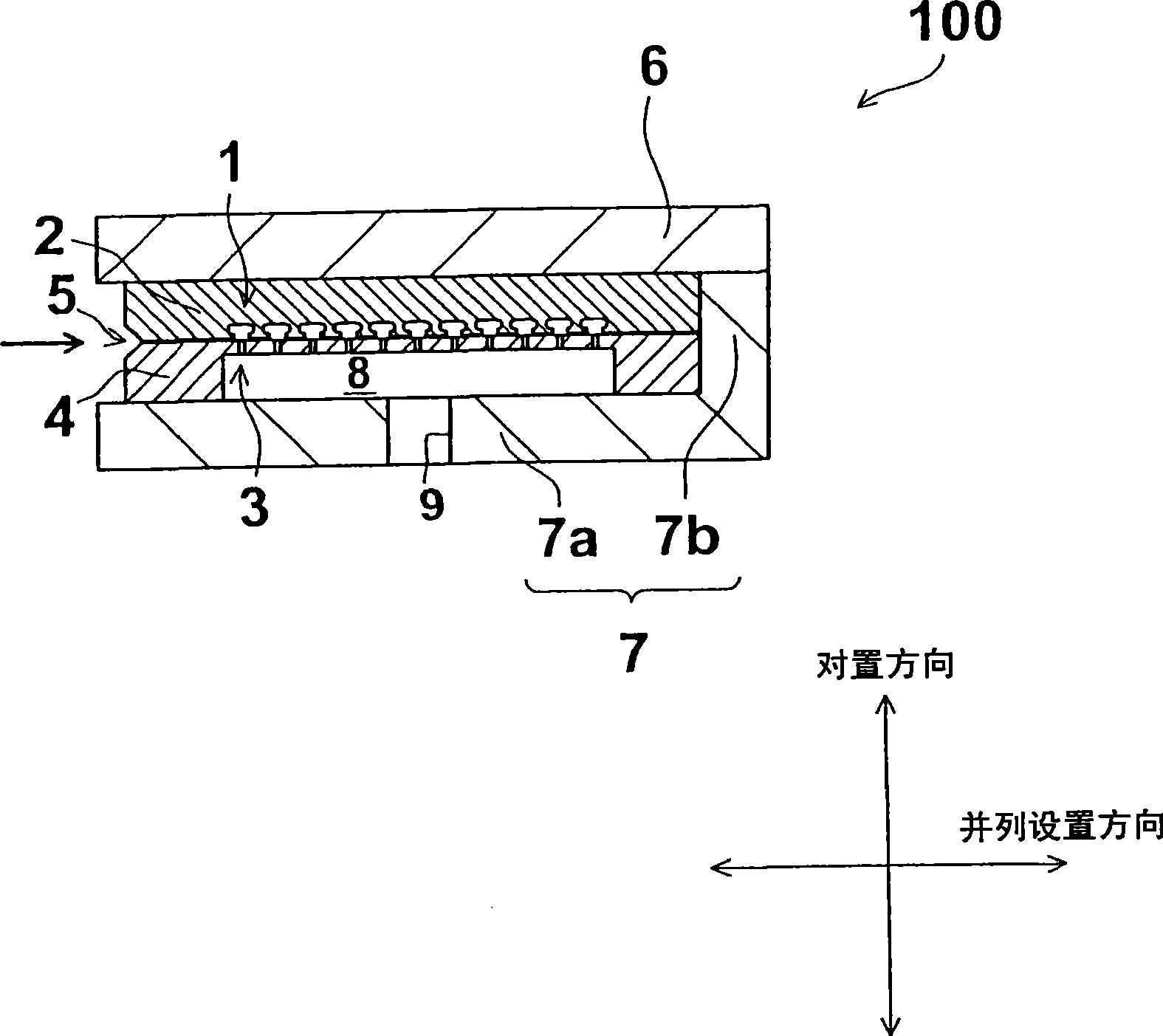
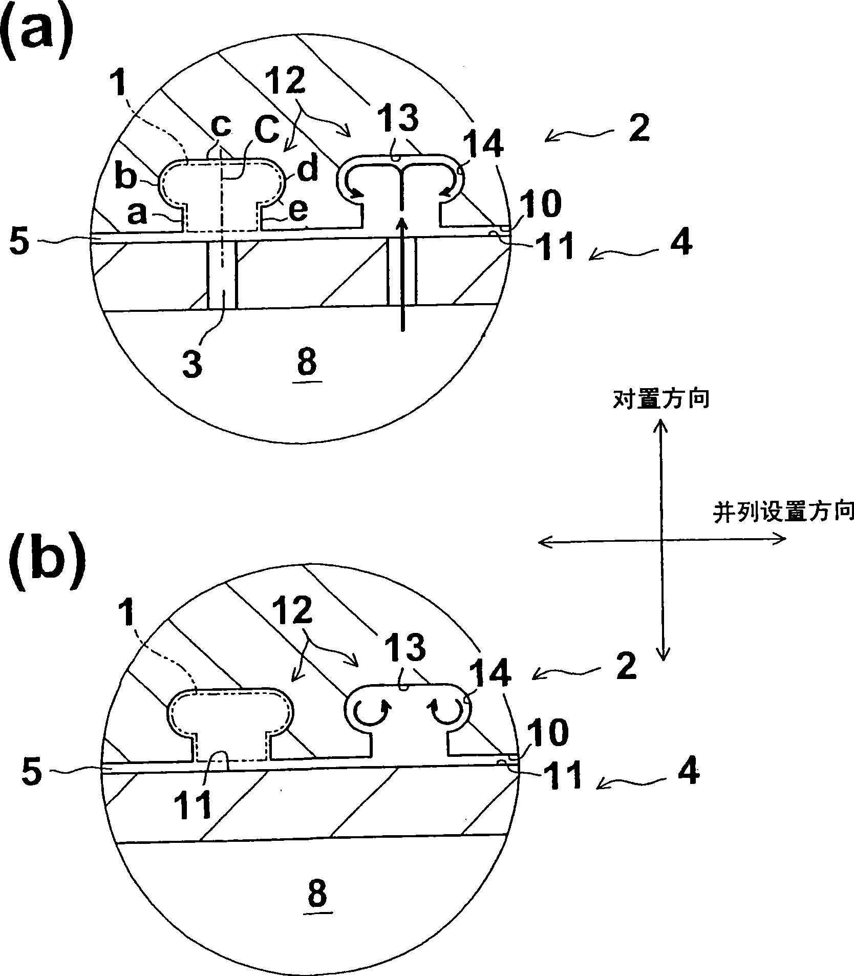
[0024] Hereinafter, a first embodiment of the present invention will be described with reference to the drawings. figure 1 It is a front view of the multi-yarn interlacing device according to the first embodiment of the present invention. figure 2 It is a front sectional view of the multi-yarn interlacing device according to the first embodiment of the present invention. image 3 It is a front partially enlarged sectional view of the multi-yarn interlacing device according to the first embodiment of the present invention.

[0025] The multi-yarn interlacing device 100 of this embodiment is a device for interlacing a plurality of multi-yarns Y. Such as figure 1 as well as figure 2 As shown, the multi-yarn interweaving device 100 has: a first member 2 (first member) forming a yarn moving space 1 in which each double yarn Y moves; and a second member 4 (second member) forming a The flow path through which the fluid injected from the yarn moving space 1 flows is the fluid in...


PUM


Abstract

The present invention provides a multiple yarn interlacing device that interlaces a plurality of yarns and which requires a reduced number of components and allows the pitch of yarn paths to be reduced, the device further having a simple configuration. The multiple yarn interlacing device includes a first member (2) having a plurality of yarn traveling spaces (1) formed as spaces through which respective multifilament yarns Y travel and a second member (4) having a plurality of fluid injecting holes (3) through which a fluid to be injected into the respective yarn traveling spaces (1) flows.

Description

technical field [0001] The present invention relates to a multi-yarn interlacing device for interlacing a plurality of yarns. Background technique [0002] As such a technique, Patent Document 1 (Japanese Patent Application Laid-Open No. 9-250043) discloses a multi-yarn fluid processing device. This multi-yarn fluid processing device has a plurality of yarn path members arranged in a row at intervals. The fluid treatment part is formed by adjacent yarn path members. [0003] However, in the structure of the above-mentioned patent document 1, it is necessary to increase the number of yarn path members according to the number of yarns which are fluid processing objects, and since the number of parts is large, it tends to stay away from it on site. Furthermore, since the yarn path members are arranged side by side, it is difficult to narrow the pitch of the yarn paths due to the complexity of the structure. Contents of the invention [0004] The present invention was made ...

Claims


Application Information

Patent Timeline
Patent Type & Authority Applications(China)
IPC IPC(8): D02J1/00D02G3/22
CPCD02J1/08D02G1/161
Inventor 笹川修文桥本欣三
Owner TMT MACHINERY INC
Features
  • R&D
  • Intellectual Property
  • Life Sciences
  • Materials
  • Tech Scout
  • Unparalleled Data Quality
  • Higher Quality Content
  • 60% Fewer Hallucinations
Learn More