
Control device, machine tool, and displaying method

A technology for control devices and working machines, applied in automatic control devices, metal processing machine parts, program control, etc., and can solve problems such as wrong internal information and trouble for operators

Inactive Publication Date: 2009-06-03
TOSHIBA MASCH CO LTD
View PDF1 Cites 4 Cited by
  • Summary
  • Abstract
  • Description
  • Claims
  • Application Information

AI Technical Summary

Problems solved by technology

[0008] However, according to such an output method, there is a problem that it is troublesome for the operator to output erroneous internal information due to a mistake in taking out the memorandum.

Method used


Image

  • Control device, machine tool, and displaying method
  • Control device, machine tool, and displaying method

Examples


Embodiment Construction

[0024] One embodiment of the present invention will be described below with reference to the drawings.

[0025] [Outline configuration of numerical controller]

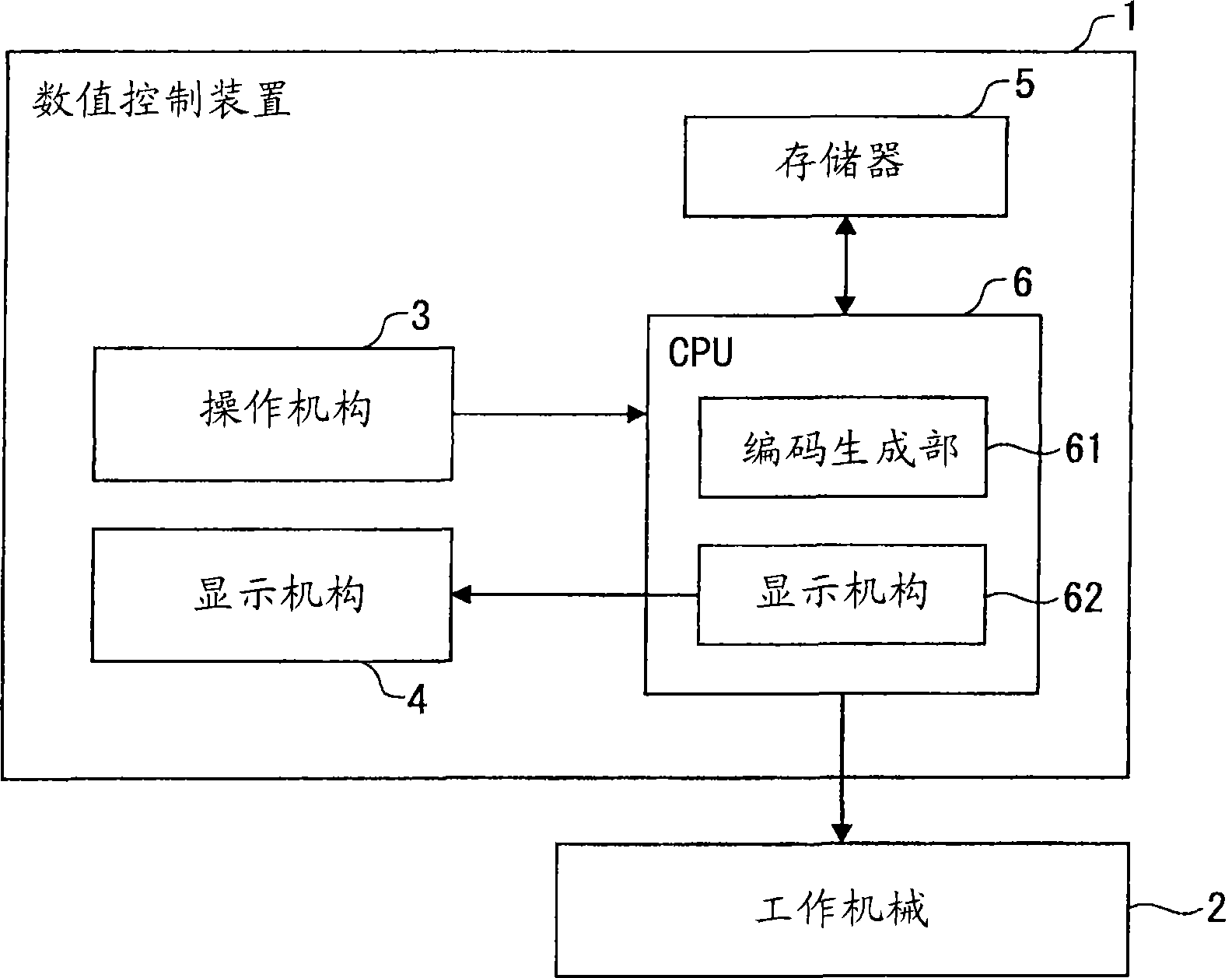
[0026] figure 1 It is a block diagram showing the schematic configuration of the numerical controller 1 and the machine tool 2 .

[0027] As a control device, the numerical control device 1 is used to control the action of the working machine 2 through numerical information and servo mechanisms, such as figure 1 As shown, the numerical controller 1 includes an operating mechanism 3 , a display mechanism 4 , a memory 5 and a CPU (Central Processing Unit) 6 .

[0028] The operation mechanism 3 is used to output to the CPU 6 an operation signal based on an operation of an operator using the numerical controller 1 , and for example, an operation panel exposed to the outside of the numerical controller 1 may be used.

[0029] The display unit 4 is used to display an image based on image information stored in a video mem...


PUM


Abstract

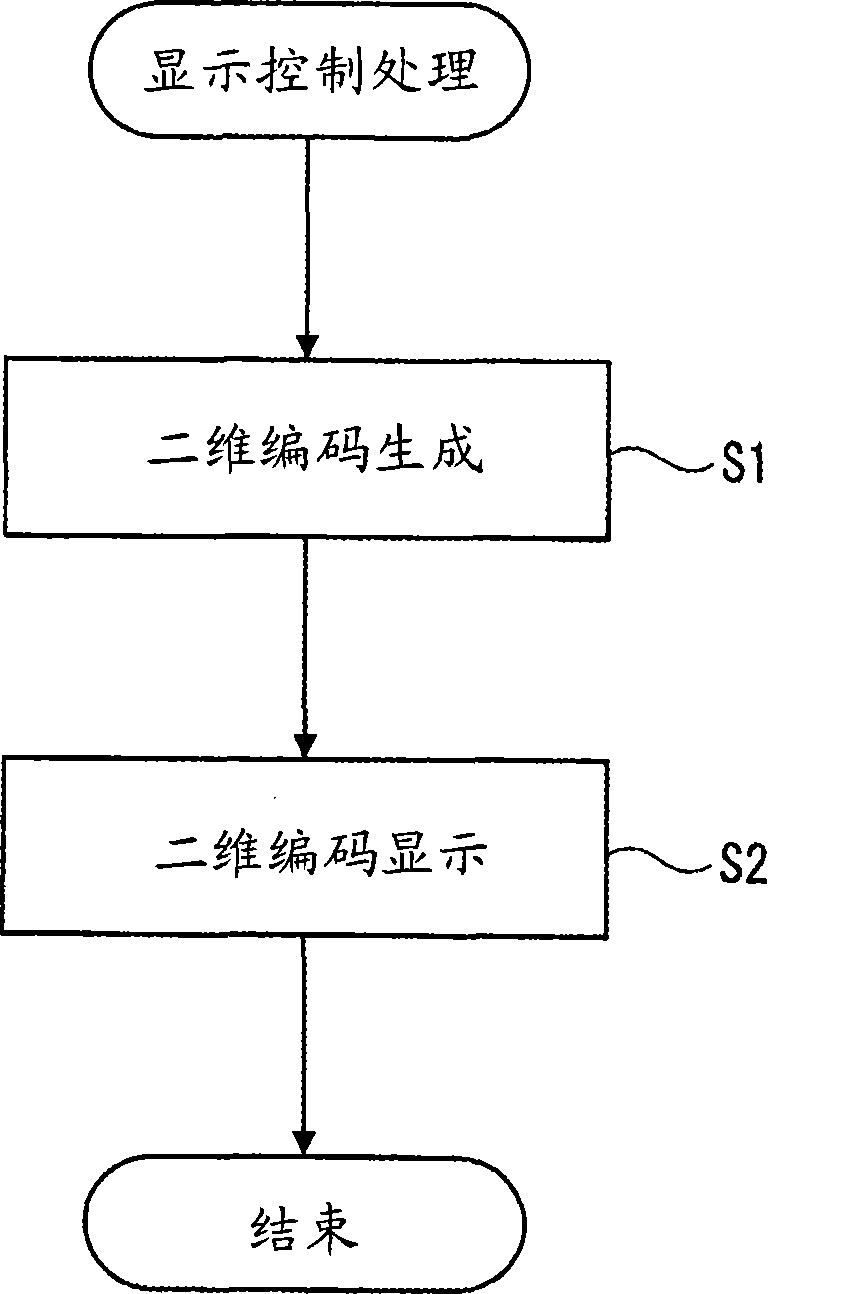
A numerical control device includes a display, a memory, and a CPU (central processing unit). The display displays an image based on image information stored in a video memory. The memory stores internal information used when a failure occurs in the numerical control device. The CPU includes a code creator and a display controller. The code creator creates a matrix two-dimensional code of the internal information stored in the memory. The display controller synthesizes image information stored in the video memory with a matrix two-dimensional code created in the code creator to display the matrix two-dimensional code on the display.

Description

technical field [0001] The invention relates to a control device, a working machine and a display method. Background technique [0002] Conventionally, a control device such as a numerical control device equipped with a display mechanism and controls the operation of a machine tool using numerical information and a servo mechanism is known (for example, refer to Document 1: Japanese Patent Application Laid-Open No. 3-78005). [0003] In addition, when a defect occurs in such a control device, it is necessary to output, for example, the version and revision of the software used to operate the control device, the state of the internal memory and I / O (Input / Output), etc. The internal information of the device (hereafter referred to as internal information) is used in the case, and the output internal information is transferred to the manufacturing place of the control device. [0004] In the numerical control device described in Document 1, by including a communication control...

Claims


Application Information

Patent Timeline
Patent Type & Authority Applications(China)
IPC IPC(8): G05B19/02G05B19/18
CPCG05B2219/23157G05B19/0428G05B2219/24103B23Q15/00G05B19/18
Inventor 小松义实富永昌登
Owner TOSHIBA MASCH CO LTD
Learn More