
Numerical controller for controlling a five-axis machining apparatus

一种数值控制器、加工设备的技术,应用在通用控制系统、程序控制、计算机控制等方向,能够解决很难线性轴平移补偿旋转补偿旋转轴平移补偿等问题,达到容易测量的效果

Active Publication Date: 2009-06-03
FANUC LTD
View PDF4 Cites 26 Cited by
  • Summary
  • Abstract
  • Description
  • Claims
  • Application Information

AI Technical Summary

Problems solved by technology

Using this technique, only rotational axis-related rotation compensation is performed for head rotation in a five-axis machining equipment by three linear axes and two rotary axes, and thus, it is difficult to perform linear-axis-related translation compensation, linear-axis-related Rotational compensation and translational compensation relative to the axis of rotation

Method used


Image

  • Numerical controller for controlling a five-axis machining apparatus
  • Numerical controller for controlling a five-axis machining apparatus
  • Numerical controller for controlling a five-axis machining apparatus

Examples


Embodiment Construction

[0047] An embodiment of a numerical controller of the present invention for controlling a five-axis machining apparatus will be described below with reference to the accompanying drawings. Five-axis machining equipment is generally classified into three types, namely, a tool head rotary type, a table rotary type, or a hybrid rotary type (in which both the tool head and the table are rotatable).

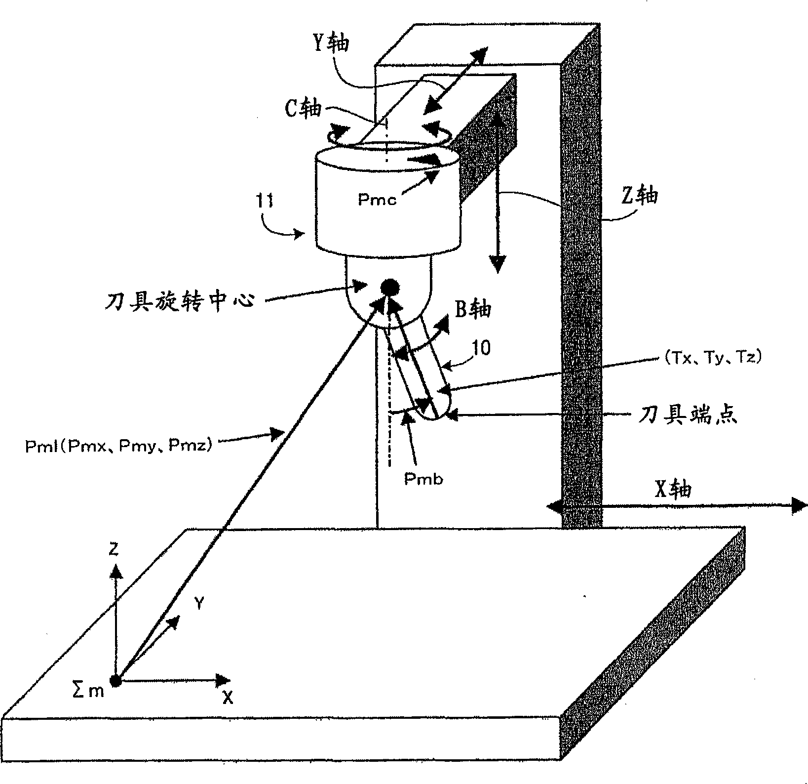
[0048] figure 1 An example five-axis switchgear is shown controlled by a numerical controller of the present invention. figure 1 The example in is the cutter head rotary type, in which the cutter head 11 rotates.

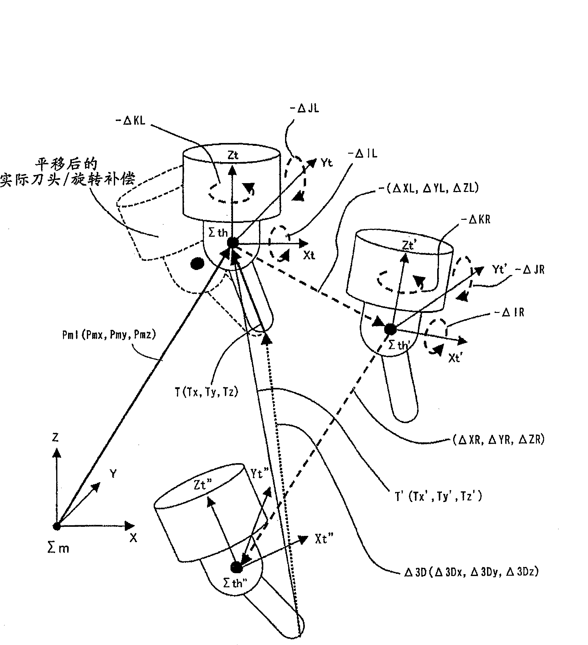
[0049] refer to figure 2 A rotation error, a translation error, and compensation for these errors in a head rotation type five-axis machining apparatus will be described. The figure shows a tool head coordinate system Sth(Xt, Yt, Zt), which has the same origin as the center of rotation of the tool head 11 . As shown in the figure, the tool head coordinate system Sth is...


PUM


Abstract

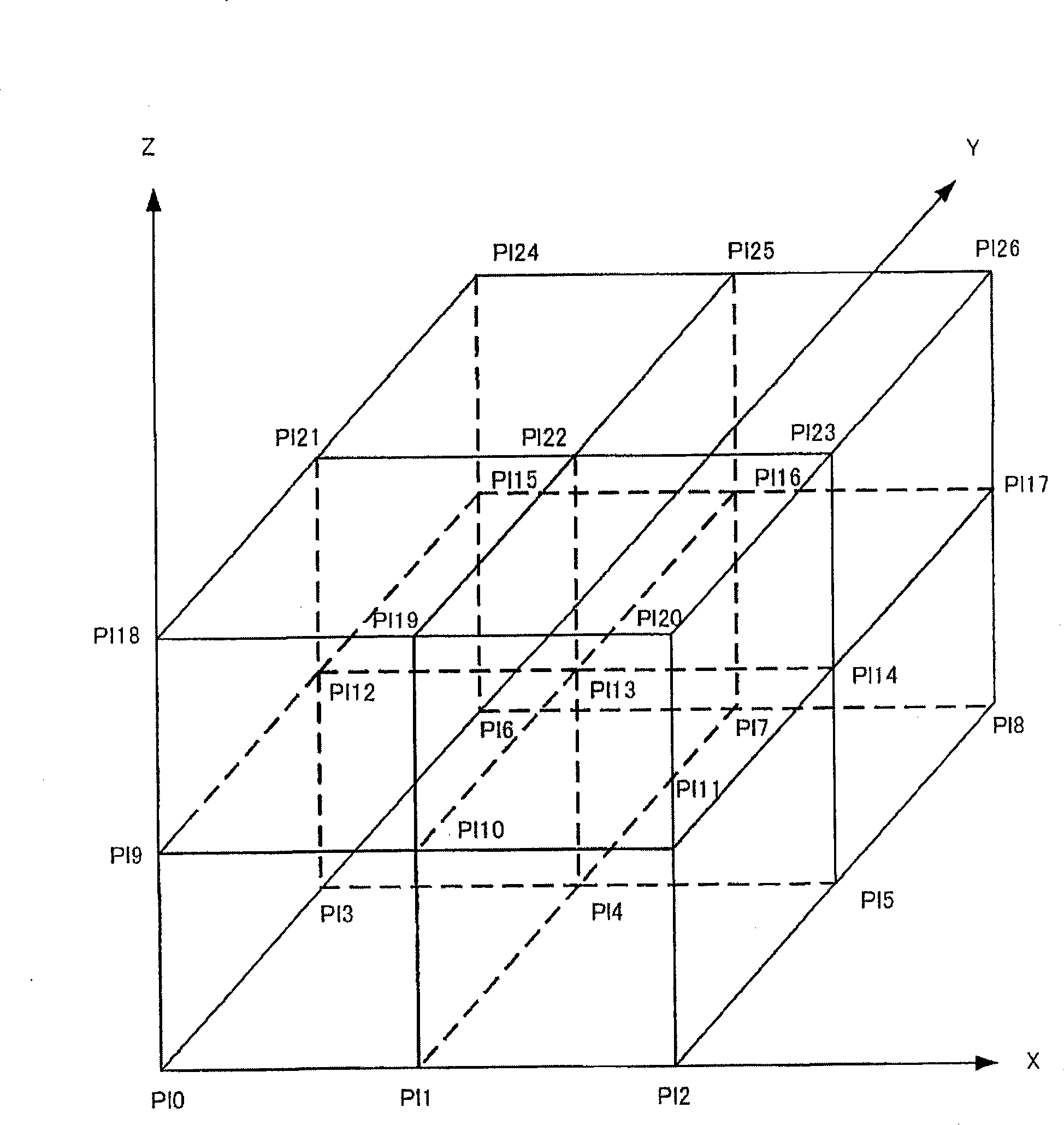
The invention provides a numerical controller for controlling a five-axis machining apparatus. The numerical controller capable of moving a tool end point position to an accurate position in a five-axis machining apparatus. Compensation amounts are set, which correspond to respective ones of a linear axis-dependent translational error, a rotary axis-dependent translational error, a linear axis-dependent rotational error, and a rotary axis-dependent rotational error, which are produced in the five-axis machining apparatus. A translational / rotational compensation amount 3D is determined from these compensation amounts and added to a command linear axis position Pm. As the compensation amounts, there is used a corresponding one of six-dimensional lattice point compensation vectors, which are determined in advance as errors due to the use of a mechanical system and measured at lattice points of lattices into which the entire machine movable region is divided.

Description

technical field [0001] The present invention relates to a numerical controller for controlling a five-axis machining apparatus having three linear axes and two rotary axes, and more particularly, to a numerical controller for performing control to High-precision machining is achieved by using compensation amounts, such as linear-axis-related and rotary-axis-related translation errors that depend on the positions of the linear and rotary axes, respectively, thereby moving the tool end point position to the correct position. Background technique [0002] JP3174704B discloses a technique in which a coordinate system is divided into lattice areas, grid point compensation vectors measured at the grid points are stored, and a current position compensation vector used in compensation is calculated based on the grid point compensation vectors . This disclosed technique only achieves linear axis-dependent translation compensation, and thus cannot perform linear axis-dependent rotati...

Claims


Application Information

Patent Timeline
Patent Type & Authority Applications(China)
IPC IPC(8): G05B19/404
CPCG05B2219/49344G05B19/404G05B2219/50297
Inventor 大槻俊明山口刚太
Owner FANUC LTD
Learn More