


Quick Research
Generate reliable direction feasibility study reports for your R&D in just a few steps.

Technical Q&A
Discover and master advanced knowledge NOW. Basics, ideas, possibilities, all at once.

Find Solutions
As an expert in R&D theories, this can generate solutions to your technical problems instantly.

Evaluate Feasibility
Analyze your overall solution with one click, know your potential R&D risks in advance.

Monitor Landscape
Get weekly tech updates, stay abreast of the latest tech innovations and key insights.
Connector for flat terminal
A technology of connectors and terminals, which is applied in the direction of connection, two-part connection devices, parts of connection devices, etc., can solve problems such as poor contact, achieve the effect of preventing poor contact and improving connection reliability
- Summary
- Abstract
- Description
- Claims
- Application Information
AI Technical Summary
Problems solved by technology
Method used
Image

Examples
Embodiment Construction
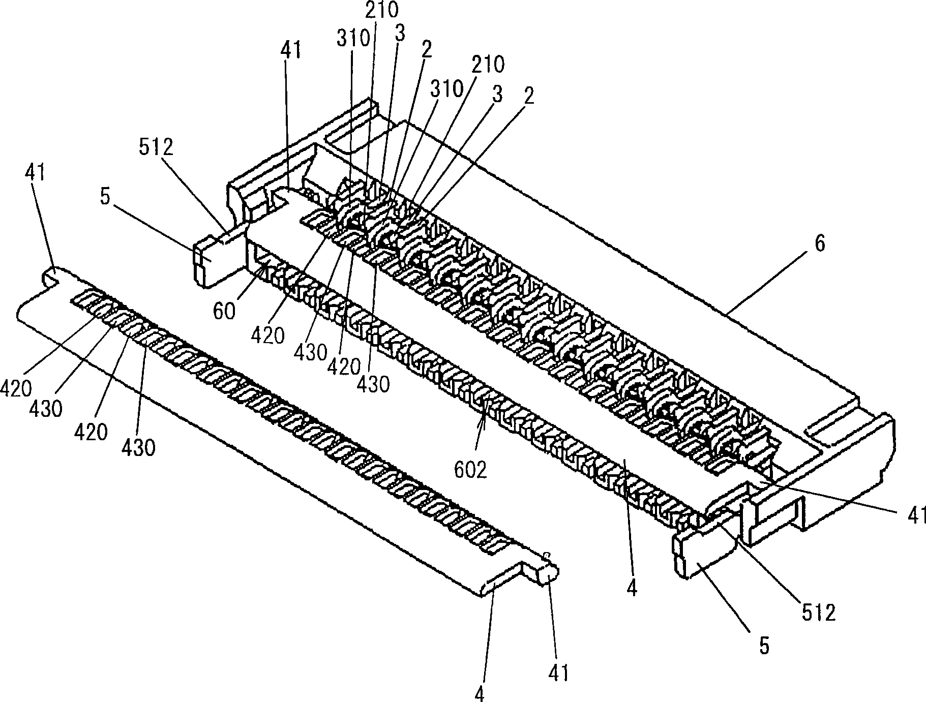
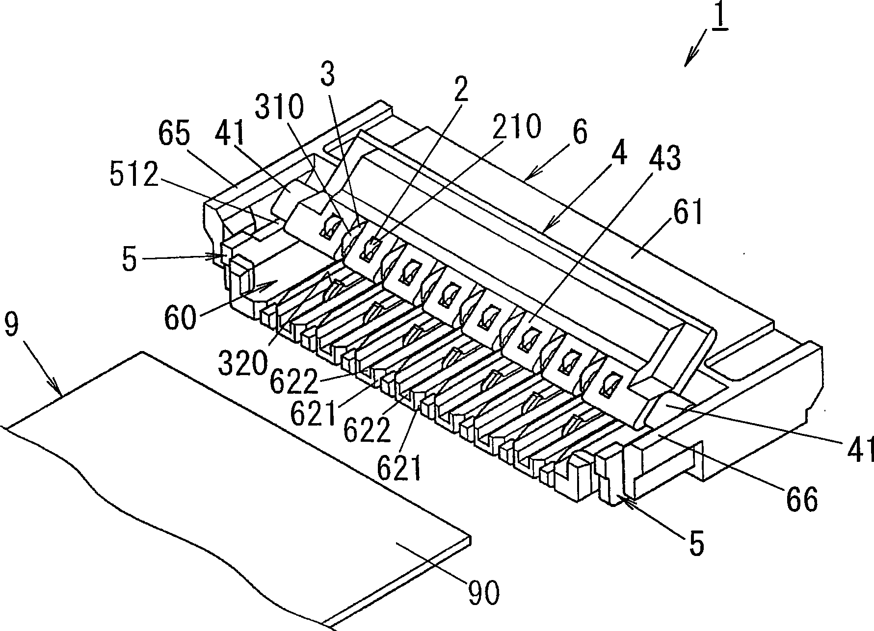
[0027] image 3 A connector for flat terminals according to an embodiment of the present invention is shown. The connector 1 is, for example, an FPC connector connected to the FPC 9, and includes at least one first contact 2, at least one second contact 3, a rod 4 made of synthetic resin, inner plates 5 and 5, and a housing 6 , the housing 6 is made of synthetic resin and has a terminal groove 60 . The shape of the terminal groove 60 corresponds to the flat terminal 90 of the FPC9. However, the flat terminal of the present invention may be one end of a flat flat cable or the like, but is not limited thereto.
[0028] exist image 3In the example of , the connector 1 is provided with eight first contacts 2 and seven second contacts 3 . The first contacts and the second contacts are made of metal, and are alternately arranged between both sides of the terminal groove 60 of the housing 6 .
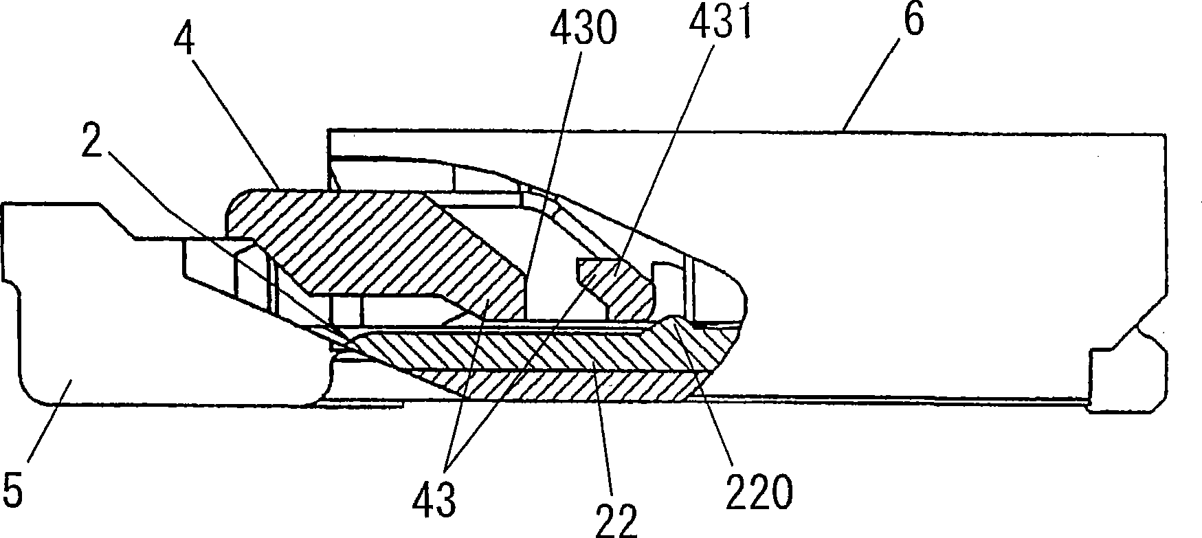
[0029] like image 3 As shown in FIG. 4 , each first contact 2 has a “U” shape and ...
PUM
 Abstract
Description
Claims
Application Information
 - R&D Engineer
- R&D Manager
- IP Professional
- Industry Leading Data Capabilities
- Powerful AI technology
- Patent DNA Extraction
Browse by: Latest US Patents, China's latest patents, Technical Efficacy Thesaurus, Application Domain, Technology Topic, Popular Technical Reports.
© 2024 PatSnap. All rights reserved.Legal|Privacy policy|Modern Slavery Act Transparency Statement|Sitemap|About US| Contact US: help@patsnap.com