Supercharge Your Innovation With Domain-Expert AI Agents!

Fluid separation device and fluid separation method thereof

A technology of fluid separation and fluid composition, applied in chemical instruments and methods, centrifuges, analytical materials, etc., can solve problems such as high cost, high manufacturing cost, and complex structure of fluid separation devices, and achieve the effect of simple structure and low cost

Active Publication Date: 2012-02-08
IND TECH RES INST
View PDF3 Cites 0 Cited by
  • Summary
  • Abstract
  • Description
  • Claims
  • Application Information

AI Technical Summary

Problems solved by technology

[0002] The structure of the known fluid separation device is usually more complex, such as the fluid separation device disclosed in US Patent No. 6,548,788, which has a micro-valve design on its cartridge to control the flow of fluid
However, since the micro-valve must be produced by micro-machining technology, the known fluid separation device cannot be produced by plastic injection molding, so the cost is relatively high
[0003] Similarly, U.S. Patent No. 5,061,381 and U.S. No. 5,089,417 also disclose other forms of fluid separation devices, whose structure is too complicated, so the manufacturing cost is relatively high

Method used


Image

  • Fluid separation device and fluid separation method thereof
  • Fluid separation device and fluid separation method thereof
  • Fluid separation device and fluid separation method thereof

Examples


Embodiment Construction

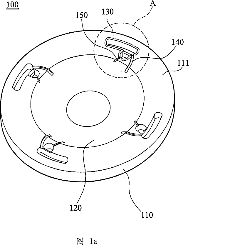
[0029] refer to Figure 1a , which is a fluid separation device 100 showing the first embodiment of the present invention, including a body 110 , a storage tank 120 , a separation unit 130 , a liquid inlet channel 140 and an exhaust channel 150 . The body 110 is circular. The storage tank 120 is circular and is formed in the center of the body 110 . The separation unit 130 is formed on the edge of the body 110 and surrounds the storage tank 120 at equal intervals. The liquid inlet channel 140 is formed on the body 110 and communicates with the storage tank 120 and the separation unit 130 . The exhaust channel 150 is formed on the body 110 and communicates with the storage tank 120 and the separation unit 130 .

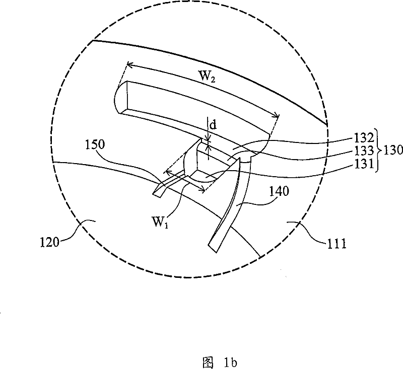
[0030] refer to Figure 1b , which is displayed Figure 1a Enlarged view of part A in . The body 110 includes a first surface 111 . The separation unit 130 includes a collecting area 131 , a stacking area 132 and a blocking wall 133 . The collection area 131 is l...


PUM


Abstract

The invention discloses a fluid separation device and a fluid separation method using the fluid separation device. The fluid separation device includes a body, a storage tank, a liquid inlet channel and a separation unit. A storage tank is formed in the center of the body. The liquid inlet channel is formed on the body and communicates with the storage tank. The separation unit is formed on the body and communicates with the liquid inlet channel. The separation unit includes a stacking area, a collecting area and a barrier wall. A collection area is located between the accumulation area and the storage tank. A barrier wall is formed between the collection area and the accumulation area.

Description

technical field [0001] The invention relates to a fluid separation device, in particular to a fluid separation device for separating blood. The invention also relates to a fluid separation method using the fluid separation device. Background technique [0002] The structure of the known fluid separation device is usually relatively complicated. For example, the fluid separation device disclosed in US Pat. No. 6,548,788 has a micro-valve design on the cassette to control the flow of fluid. However, since the micro-valve must be produced by micro-machining technology, the known fluid separation device cannot be produced by plastic injection molding, so the cost is relatively high. [0003] Similarly, US Pat. No. 5,061,381 and US 5,089,417 also disclose other forms of fluid separation devices, but their structures are too complicated, so the manufacturing cost is relatively high. Contents of the invention [0004] The present invention provides a fluid separation device for...

Claims


Application Information

Patent Timeline
Patent Type & Authority Patents(China)
IPC IPC(8): B04B5/04B01L3/00G01N33/49G01N35/00
Inventor 蔡忠宪钟正煦谢文彬
Owner IND TECH RES INST
Features
  • R&D
  • Intellectual Property
  • Life Sciences
  • Materials
  • Tech Scout
  • Unparalleled Data Quality
  • Higher Quality Content
  • 60% Fewer Hallucinations
Learn More