
Dual volume pump

A dual-capacity, capacity technology, applied in pumps, variable-capacity pump components, multi-cylinder pumps, etc., can solve the problem that the pump discharge capacity cannot be set to zero, and achieve the effect of reliable pressure compensation

Inactive Publication Date: 2013-07-24
TOKYO KEIKI
View PDF1 Cites 0 Cited by
  • Summary
  • Abstract
  • Description
  • Claims
  • Application Information

AI Technical Summary

Problems solved by technology

[0008] However, in the double displacement pump described in Patent Document 1, there is a problem that the displacement of the pump cannot be set to zero because the position of the swash plate 50a is restricted by the abutment position adjustment screw mechanism 52b to define a small displacement.

Method used


Image

  • Dual volume pump
  • Dual volume pump
  • Dual volume pump

Examples


Embodiment Construction

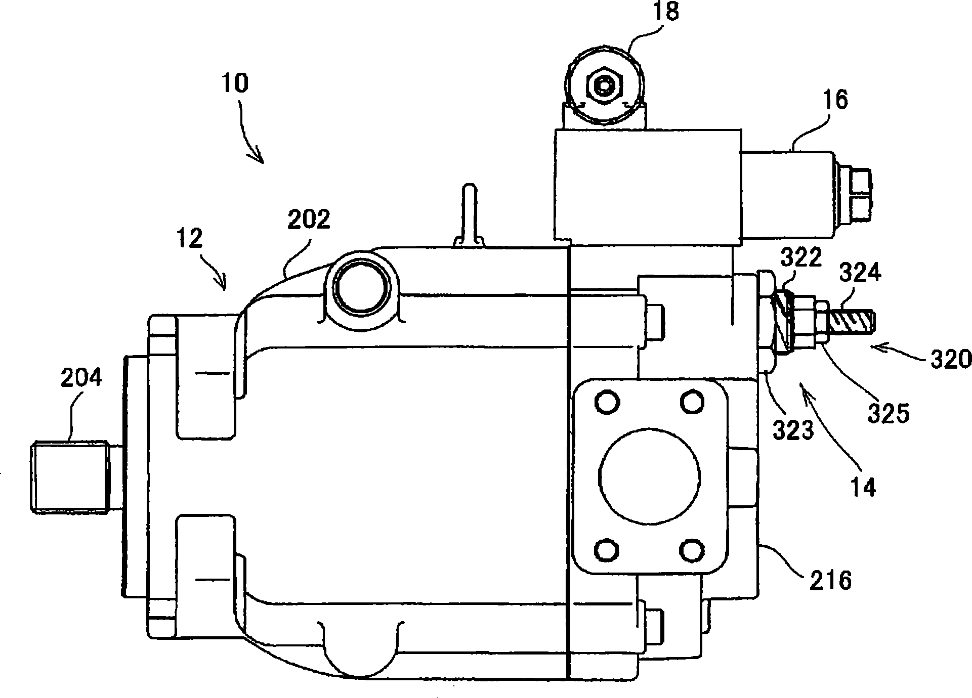
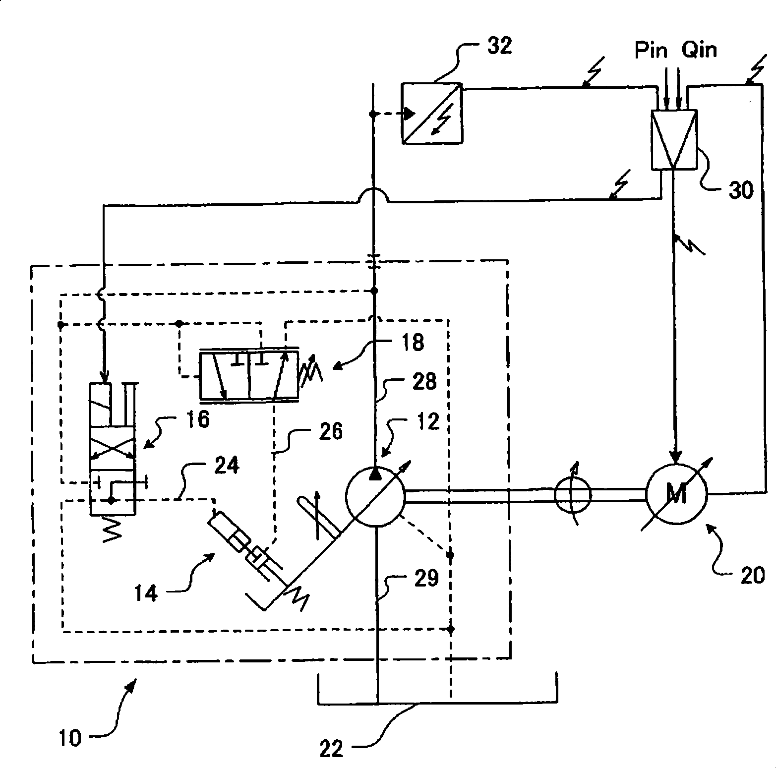
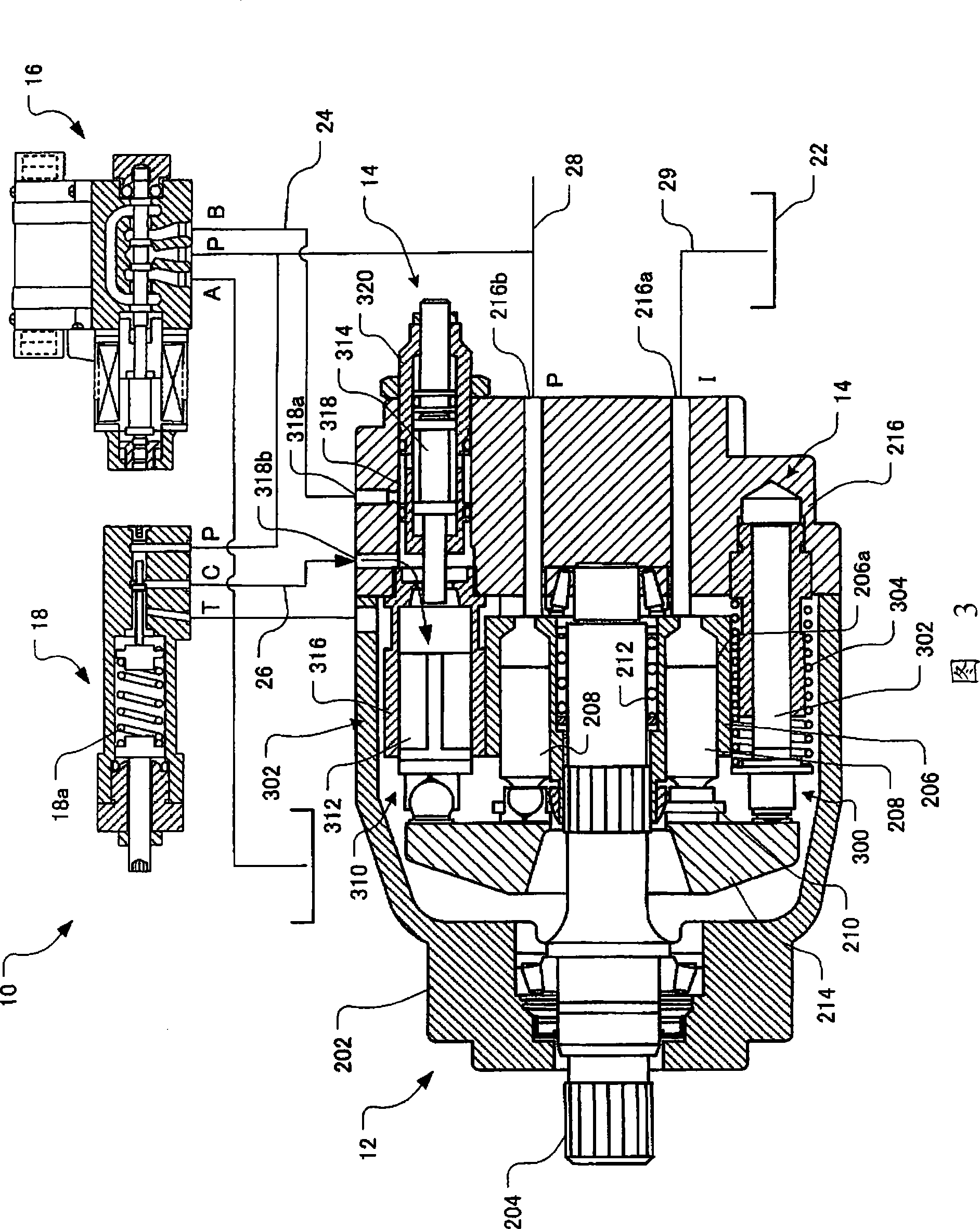
[0039] Embodiments of the present invention will be described below using the drawings. figure 1 is the appearance diagram of the double capacity pump of the present invention, figure 2 It is a circuit diagram, and Fig. 3 is a structural sectional view of the dual capacity pump.

[0040] exist figure 2Among them, the dual capacity pump 10 includes: a pump main body 12, which is rotationally driven to suck and discharge liquid; a variable capacity mechanism 14, which can change the discharge capacity per unit rotation of the pump main body 12; and a capacity switching valve 16, which The high-pressure side flow path and the low-pressure side flow path are selectively communicated with the pressure guide passage, and the pressure guide passage communicates with the pressure receiving part of the variable displacement mechanism 14, and the dual displacement pump 10 also has a pressure compensating mechanism. Compensation valve 18. The pump body 12 of the dual displacement p...


PUM


Abstract

A two-capacity pump is provided to control the discharge capacity by converting the pressure to a pressure receiving part of a capacity varying mechanism. A two-capacity pump comprises: a pump body(12), a capacity variableness tool(14), a capacity diverter(16) and a pressure compensation tool. The pump body inhales and discharges the rotated liquid. The capacity variableness tool varies the discharged capacity per the unit rotation of the pump body. The capacity variableness tool selectively diversifies the high pressure side flow path and the low pressure side flow path to a pressure guide path(24). The pressure compensation tool reduces the discharge capacity of the pump body to be smaller according to the discharge pressure of the pump body.

Description

technical field [0001] The present invention relates to a dual capacity pump which is a variable capacity type pump capable of switching its discharge capacity to any of a large capacity and a small capacity, and capable of switching between a large capacity and a small capacity. work stably. Background technique [0002] Conventionally, a dual displacement pump described in Patent Document 1 is known as such a dual displacement pump. The dual capacity pump is as Figure 12 The structure shown in the circuit diagram and structural cross-sectional view of the pump body 50 includes: a pump main body 50, which is rotationally driven to suck and discharge liquid; a variable capacity mechanism 52, which can change the discharge capacity per unit rotation of the pump main body 50; and switch The valve 54 selectively communicates the high-pressure side flow path of the discharge pressure and the low-pressure side flow path of the suction pressure with a pressure guiding path that ...

Claims


Application Information

Patent Timeline
Patent Type & Authority Patents(China)
IPC IPC(8): F04B49/12F04B49/22F04B1/04
CPCF04B49/06F04B49/002F04B1/324F04B1/2042
Inventor 兵藤训一田村大亮
Owner TOKYO KEIKI
Learn More