Winding current waveform controlling method for switch reluctance motor braking process

A technology of winding current and braking process, applied in the direction of stopping device, etc., can solve the problems of unfavorable reduction of motor output torque ripple, poor smoothness of current waveform, large fluctuation of winding current, etc., and achieves small current change rate and fast response. , the effect of reducing electromagnetic interference

Inactive Publication Date: 2009-06-10
BEIJING CHINA TEX MECHANICAL & ELECTRICAL ENG
View PDF0 Cites 10 Cited by
  • Summary
  • Abstract
  • Description
  • Claims
  • Application Information

AI Technical Summary

Problems solved by technology

But if the motor speed is high, then Relatively large, and R i can be ignored, using zero voltage, it can be seen from formula 2 that the current rises at a faster rate; if positive pressure is used, it can be seen from formula 1 that the current rises fa

Method used


Image

  • Winding current waveform controlling method for switch reluctance motor braking process
  • Winding current waveform controlling method for switch reluctance motor braking process
  • Winding current waveform controlling method for switch reluctance motor braking process

Examples


Embodiment Construction

[0032] Relevant technical content and detailed description of the present invention, now cooperate accompanying drawing to explain as follows:

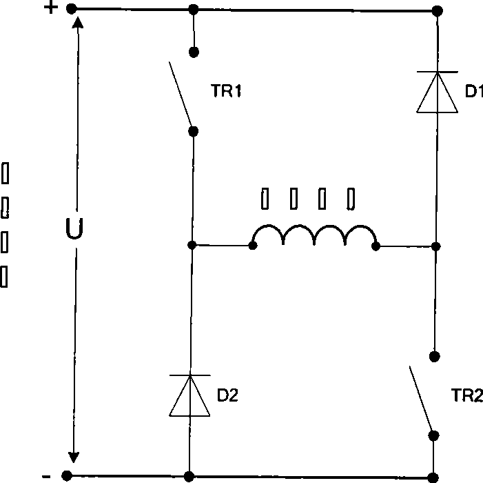
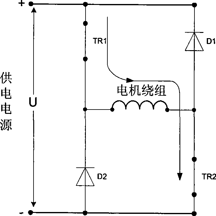
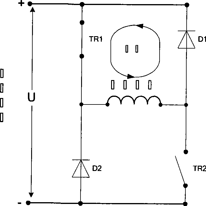
[0033] The invention provides a winding current waveform control method in the braking process of a switched reluctance motor. It is suitable for switched reluctance motors with any number of phases and any structure powered by an independent half-bridge power circuit for each phase winding. The half-bridge power circuit includes 2 power switches and 2 freewheeling diodes. Figure 5 It is a schematic diagram of the waveform control principle of the winding current in the present invention. Such as Figure 5 As shown, according to the angular position of the motor rotor and the selected control waveform, the given winding current is distributed, the current given value is compared with the winding current feedback value, and a control signal is generated according to the relationship between the two to control the power switch to be t...


PUM


Abstract

The invention provides a method for controlling the winding current waveform in the braking process of a switch reluctance motor, which comprises: a step of braking operation by the motor, during which the positive voltage is adopted to increase the current in the initial segment of the electrifying interval; a step of adopting negative voltage to reduce the current after the current increases to the specified value and the winding current is larger than the specified current; a step of increasing the winding current by adopting zero voltage when the winding current is less than the specified current; and a step of adopting the positive voltage compensation to increase the current if the winding current is reduced when zero voltage is adopted or the current does not increase to the specified value after the zero voltage with n periods is adopted continuously. The method has the advantages that the braking current waveform of the winding can track the specified waveform well, the current waveform has good smooth property, and the output torque pulse of the motor is effectively reduced.

Description

technical field [0001] The invention relates to a current control method, in particular to a winding current waveform control method suitable for the braking process of a switched reluctance motor with any number of phases and any structure powered by an independent half-bridge power circuit for each phase winding. Background technique [0002] The stator and rotor of the switched reluctance motor are double salient pole structures, which are made of laminated silicon steel sheets. There are concentrated windings on the stator poles and no windings on the rotor. Switched reluctance motors can be designed with different winding phases and different stator and rotor poles, such as three-phase 6 / 4 poles, three-phase 12 / 8 poles, four-phase 8 / 6 poles. [0003] The switched reluctance motor is powered by the power circuit, figure 1 It is a topology of a one-phase power circuit with two switches. The power supply in the figure can be a storage battery or a rectified and filtered...

Claims


Application Information

Patent Timeline
IPC IPC(8): H02P6/24
Inventor 毕伟苏建中
Owner BEIJING CHINA TEX MECHANICAL & ELECTRICAL ENG
Why Eureka
Try Eureka