Stepless variable drive of stepless transmission

A continuously variable transmission, continuously variable speed technology, applied in the direction of transmission, belt/chain/gear, mechanical equipment, etc., can solve the problems of easy wear and tear of transmission belt or transmission chain, sluggish transmission of power, etc.

Inactive Publication Date: 2009-06-17
麦锡汕 +1
View PDF0 Cites 6 Cited by
  • Summary
  • Abstract
  • Description
  • Claims
  • Application Information

AI Technical Summary

Problems solved by technology

[0009] In order to solve the problems that the transmission belt or transmission chain of the continuously variable transmission of the prior art is easy to wear, the phenomenon of stagnation in the speed change, and the transmission power are small, the present inv

Method used


Image

  • Stepless variable drive of stepless transmission
  • Stepless variable drive of stepless transmission
  • Stepless variable drive of stepless transmission

Examples


Embodiment approach 1

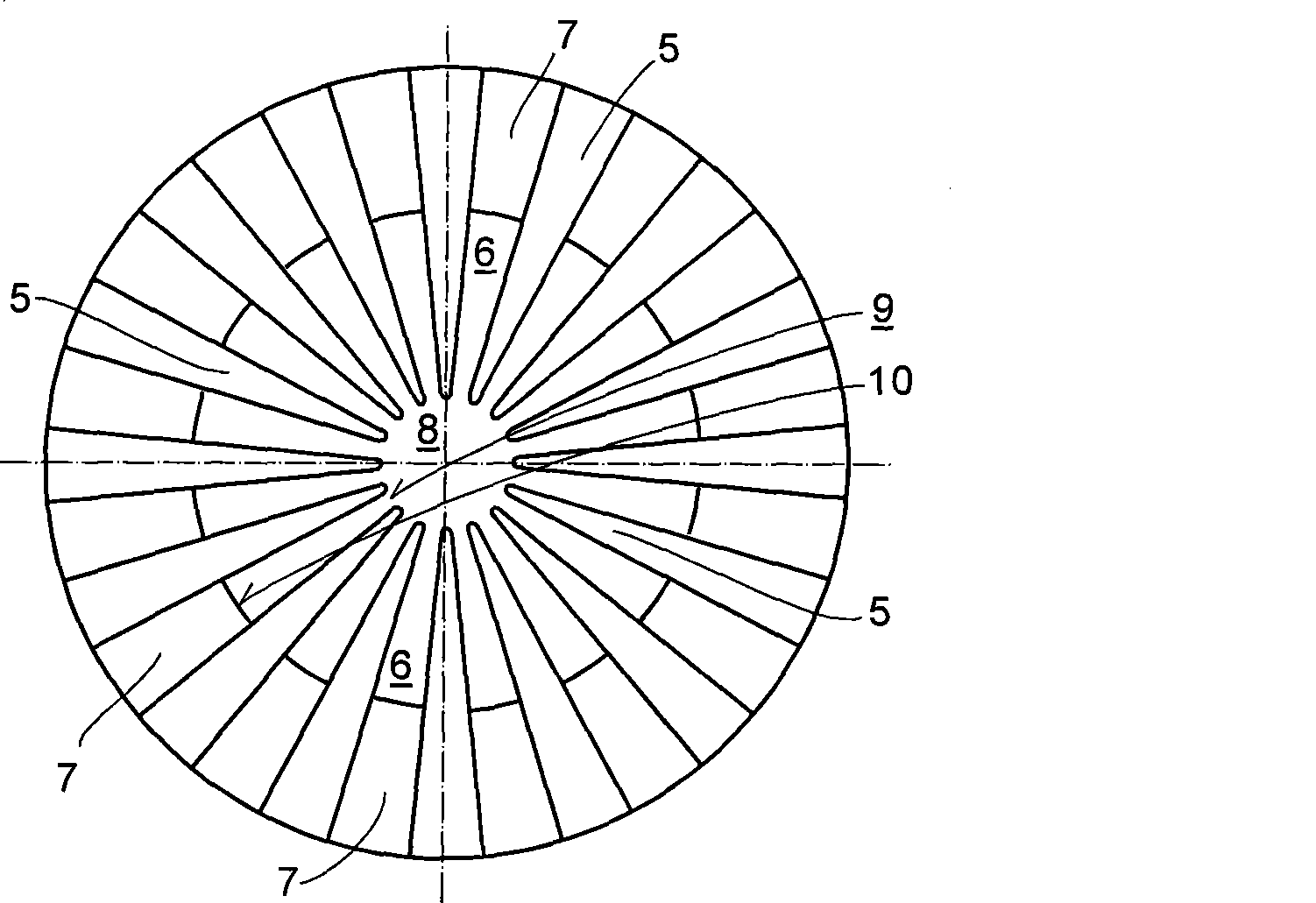
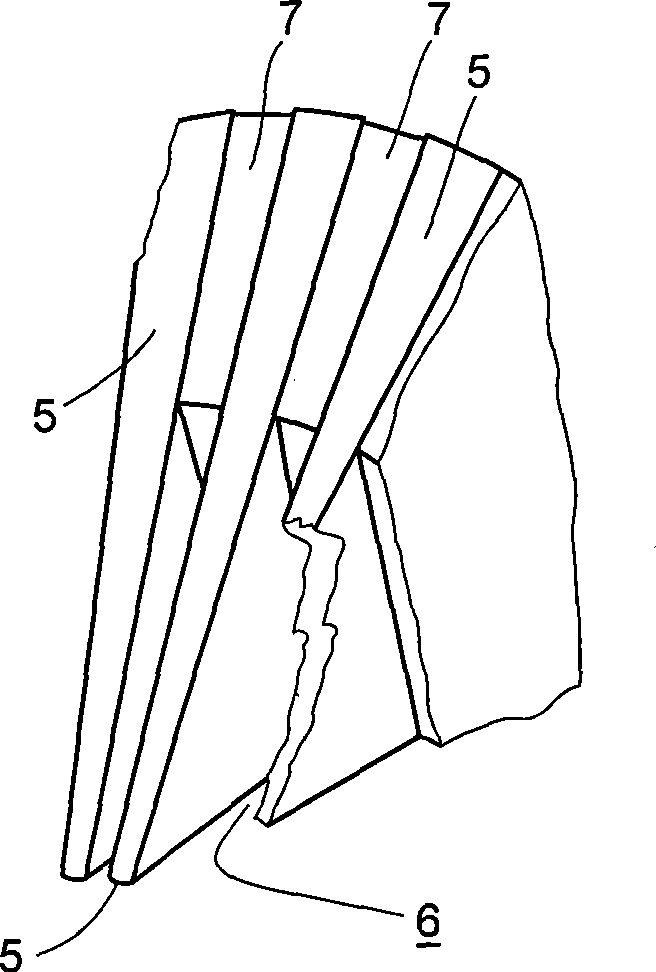
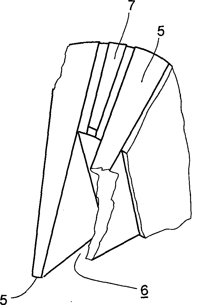
[0040] Implementation mode one: figure 1 Shown is the front view of the cone disc. It can be seen from the figure that fan-shaped grooves 6 and fan-shaped spokes 5 are arranged alternately on the front of the cone disc, and the inner narrow end 9 of the fan-shaped groove 6 communicates with the shaft hole 8. In this figure, the area 7 extending from the outer wide end 10 of the fan-shaped groove 6 to the large end of the cone disk is a plane with its four corners as the base point. figure 2 Then the appearance of the area 7 is displayed more intuitively. The area 7 adopts such a plane, so that the transmission belt and its outer hoop chain can smoothly move outward when the pulley expands the transmission radius. If the area 7 has a large circumferential span, a radial ridge block with an inner slope can also be retained in the middle, such as image 3 As shown, ridged blocks increase the circularity of the cone disc. Figure 4 , Figure 5 What is shown is that the two cone disc...

Embodiment approach 2

[0042] Implementation mode two: such as Figure 18 with Figure 20 As shown, the two edges of the fan-shaped spokes 5 on the front face of the cone have a chamfered surface 19 that is closer to the larger end of the cone and forms a chamfered surface 19, and at the same time, each layer of the steel ring belt 13 and each layer of the transmission belt 12 are loose The steel endless belt 13' is provided with elongated holes 20 on both sides of the plane, and an outer hoop chain 14 narrower than the corresponding position of the V-shaped ring groove of the transmission pulley is adopted. When working, the steel endless belt 13 and the loose steel endless belt 13' of the transmission belt 12 are crushed by the elongated holes 21 at the pressing position of the fan-shaped spokes 5, and the steel endless belt 13 and the loose steel endless belt 13' are compressed. Correspondingly, there is a slight indentation, forming the friction between the fan-shaped spokes 5 and the transmission b...


PUM


Abstract

The invention discloses a stepless speed change device of continuously variable transmission (CVT), both the driving pulley and the driven pulley of which are formed by inserting movable cone plate and fixed cone plate alternately. Alternately arranged fan-shaped groove (6) and fan-shaped spoke (5) are arranged on each cone plate surface, both cone plates of one pulley can do to-and-fro sliding movement by inserting its fan-shaped spoke (5) into the other fan-shaped groove (6), and driving radius of pulley is altered by changing insertion level. The two alternately inserted cone plates can form a pulley the V-shaped ring groove of which is larger than 45 DEG, the transmission of power is realized by tense friction force for the two pulleys and transmission belts comprised of multilayer steel endless belts, and the transmission belts can bear stretching force that can produce huge friction force, therefore, the transmission powder is great; and if external goop chain and internal laxation layer are applied, the effect will be much better. Meanwhile, the main force applied to the transmission belt by the pulley is outward radial force, and movements are smooth when the driving radius is enlarged. In addition, the friction of idle work does not exist when the transmission belts pass in and out of the pulley, therefore, the service life of the stepless speed change device is long.

Description

Technical field [0001] The invention relates to a CVT continuously variable transmission for vehicles, in particular to a continuously variable transmission device of a continuously variable transmission. Background technique [0002] The continuously variable transmission installed on today's cars is a new type of high-efficiency transmission. "The principle and maintenance of the latest car continuously variable transmission" (ISBN 978-7-5381-4803-9) is edited by Luan Qiwen and Yu Jingnuo. In the book, the structure principle of the continuously variable transmission of Dongfeng Nissan Sylphy sedan is disclosed, as well as the structure principle of the continuously variable transmission of Guangzhou Honda Fit sedan, Audi A6 / A4 sedan, Fiat sedan, Ford Fiesta passenger car and other vehicles. Although there are many differences between the continuously variable transmissions of the above-mentioned vehicles, their core part, the continuously variable transmission device, is the s...

Claims


Application Information

Patent Timeline
IPC IPC(8): F16H9/20
Inventor (请求不公开姓名)
Owner 麦锡汕
Why Eureka
Try Eureka