Double gate valve

A gate valve and valve body technology, which is applied in the field of double gate valves of vacuum equipment, can solve problems such as troublesome operation, short service life, and non-two-way sealing

Active Publication Date: 2009-06-17
广东瑞迅精密机械有限公司
View PDF0 Cites 10 Cited by
  • Summary
  • Abstract
  • Description
  • Claims
  • Application Information

AI Technical Summary

Problems solved by technology

[0002] At present, the double gate valves used in vacuum equipment generally have defects such

Method used


Image

  • Double gate valve
  • Double gate valve
  • Double gate valve

Examples


Embodiment Construction

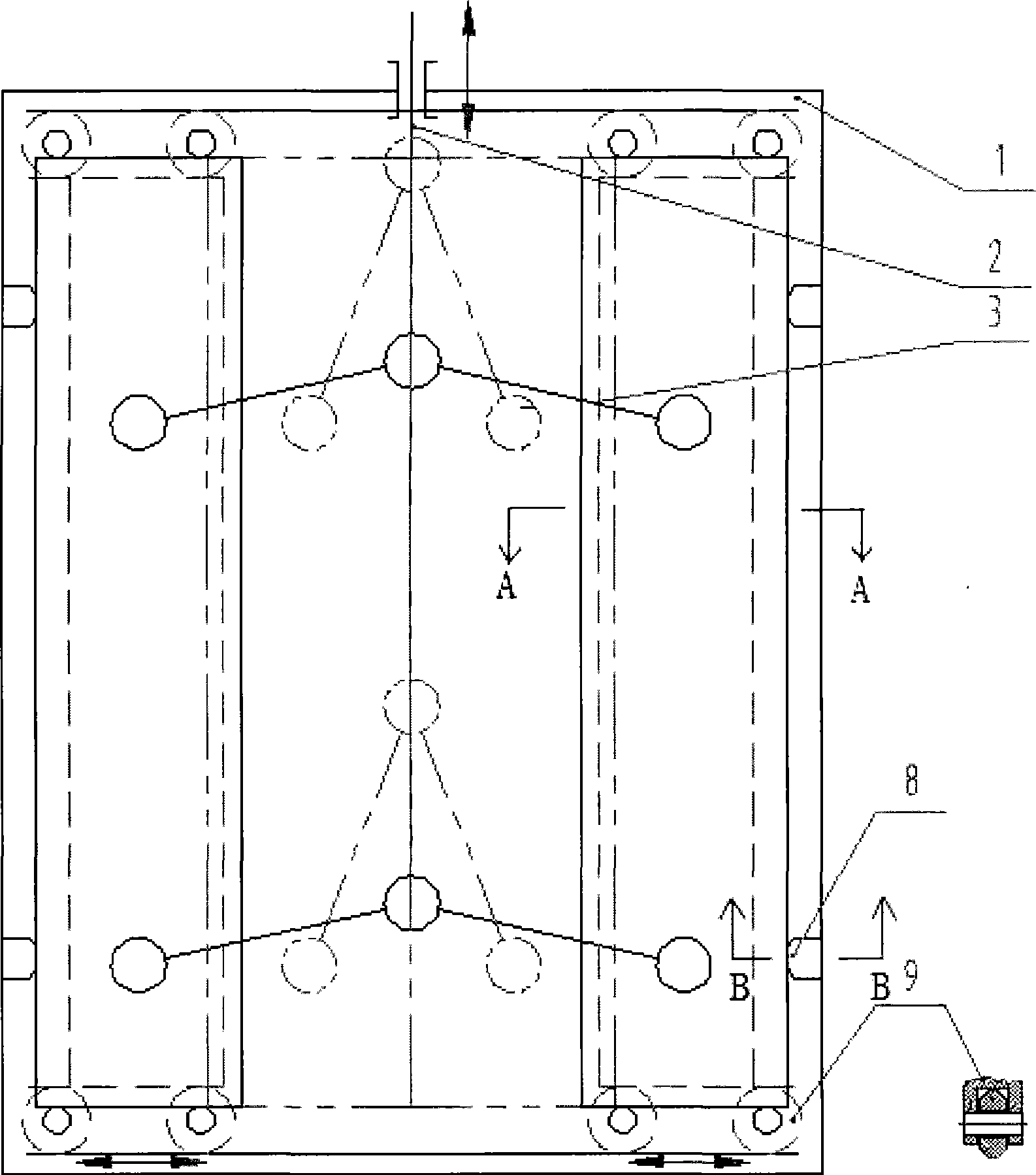
[0017] figure 1 is a structural schematic diagram of a double gate valve according to the present invention. The double gate valve includes a valve body, a driving device, a stop device and a valve device, wherein the driving device and the valve device are movably installed on the valve body, and the driving device is connected with the valve device to form a parallel A quadrilateral mechanism, the stop device is installed on the valve body.

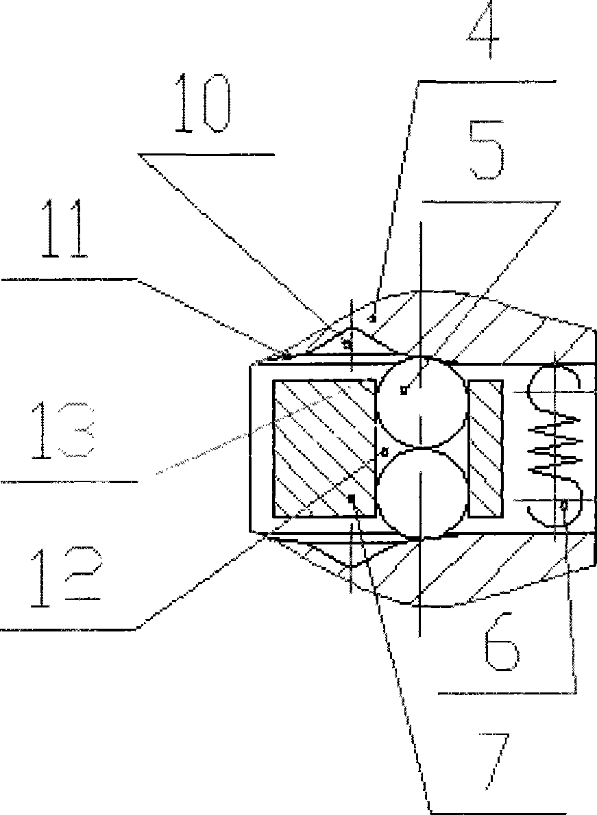
[0018] According to a preferred embodiment of the present invention, the double gate valve includes two valve devices, which are symmetrically arranged with respect to the valve stem 2, wherein each valve device includes a drive plate 7, a spring 6, a steel ball 5 , roller 9 and two valve plates 4. The valve plate 4 is floatingly supported on the driving plate 7 by the spring 6 and the steel ball 5 . Such as figure 2 As shown, a hole 12 is arranged in the drive plate 7, and two steel balls 5 are placed in the hole 12. The diameter...


PUM


Abstract

The invention relates to a double gate valve for vacuum equipment. The double gate valve comprises a valve body, a driving device, a stopping device and a valve device, wherein the driving device and the valve device are movably arranged on the valve body; the driving device is connected with the valve device to form a parallelogram mechanism; the stopping device is arranged on the valve body. The driving device can drive the valve to open or close the valve device. The double gate valve can be rapidly opened, and can be reliably locked. Moreover, the plane surface of the valve has zero friction, so the double gate valve has long service life.

Description

technical field [0001] The invention relates to a double gate valve, more specifically, to a double gate valve for vacuum equipment. Background technique [0002] At present, the double gate valves used in vacuum equipment generally have defects such as complex structure, troublesome operation, non-bidirectional sealing and short service life. In order to overcome the above-mentioned defects of the known double gate valve, the present invention proposes a novel double gate valve. Contents of the invention [0003] The invention is an improvement on the prior art, and the technical problem to be solved is to provide a double gate valve suitable for controlling non-circular valves. According to the double gate valve of the present invention, two valves can be opened simultaneously, and the opening speed is fast, the self-locking is reliable, and two-way sealing is possible. Because the plane of the valve port has no friction, the double gate valve of the present invention ...

Claims


Application Information

Patent Timeline
IPC IPC(8): F16K3/314F16K31/00F16K31/122F16K51/02F16K37/00
Inventor 丁东胜李初春
Owner 广东瑞迅精密机械有限公司
Why Eureka
Try Eureka