Compact wafer automatic transfer unit

An automatic transmission and compact technology, applied in the direction of transportation and packaging, conveyor objects, etc., can solve the problem of reducing the overall height, and achieve the effect of reducing the overall height and width, reasonable structure design, and compact structure design.

Active Publication Date: 2011-12-21
SHANGHAI FORTREND TECH CO LTD
View PDF7 Cites 6 Cited by
  • Summary
  • Abstract
  • Description
  • Claims
  • Application Information

AI Technical Summary

Problems solved by technology

[0013] The purpose of the present invention is to provide a compact wafer automatic transfer device, which can effectively overcome its structural limitations and cannot be applied in addition to inheriting the advantages of providing a clean microenvironment from the isolation technology in the SMIF in the prior art. Due to the shortcomings of complex actions in the narrow space of the process equipment, the structure design of the device is more compact, and its overall height is significantly reduced, leaving more operating space for the process equipment. The transmission operation is more stable, and the action is more flexible and reliable. Further expansion The scope of application is widened, so that it can realize the flipping of the wafer cassette in the range of 0-90 degrees in the limited travel space, and set the tilt angle at will, so as to complete the automatic transmission of the wafer in horizontal or vertical state, and at the same time realize the wafer cassette Translate left and right to adapt to automatic transmission in a narrow space where the center distance of process equipment arranged side by side is smaller than the center distance of transmission equipment, and it can be flexibly stopped when encountering external interference to achieve a precisely controlled transmission effect

Method used


Image

  • Compact wafer automatic transfer unit
  • Compact wafer automatic transfer unit
  • Compact wafer automatic transfer unit

Examples


Embodiment Construction

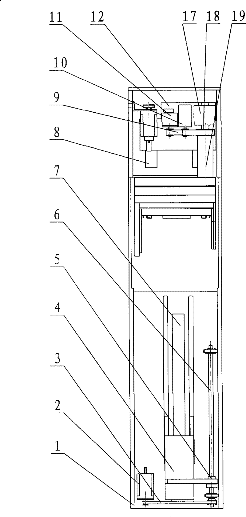
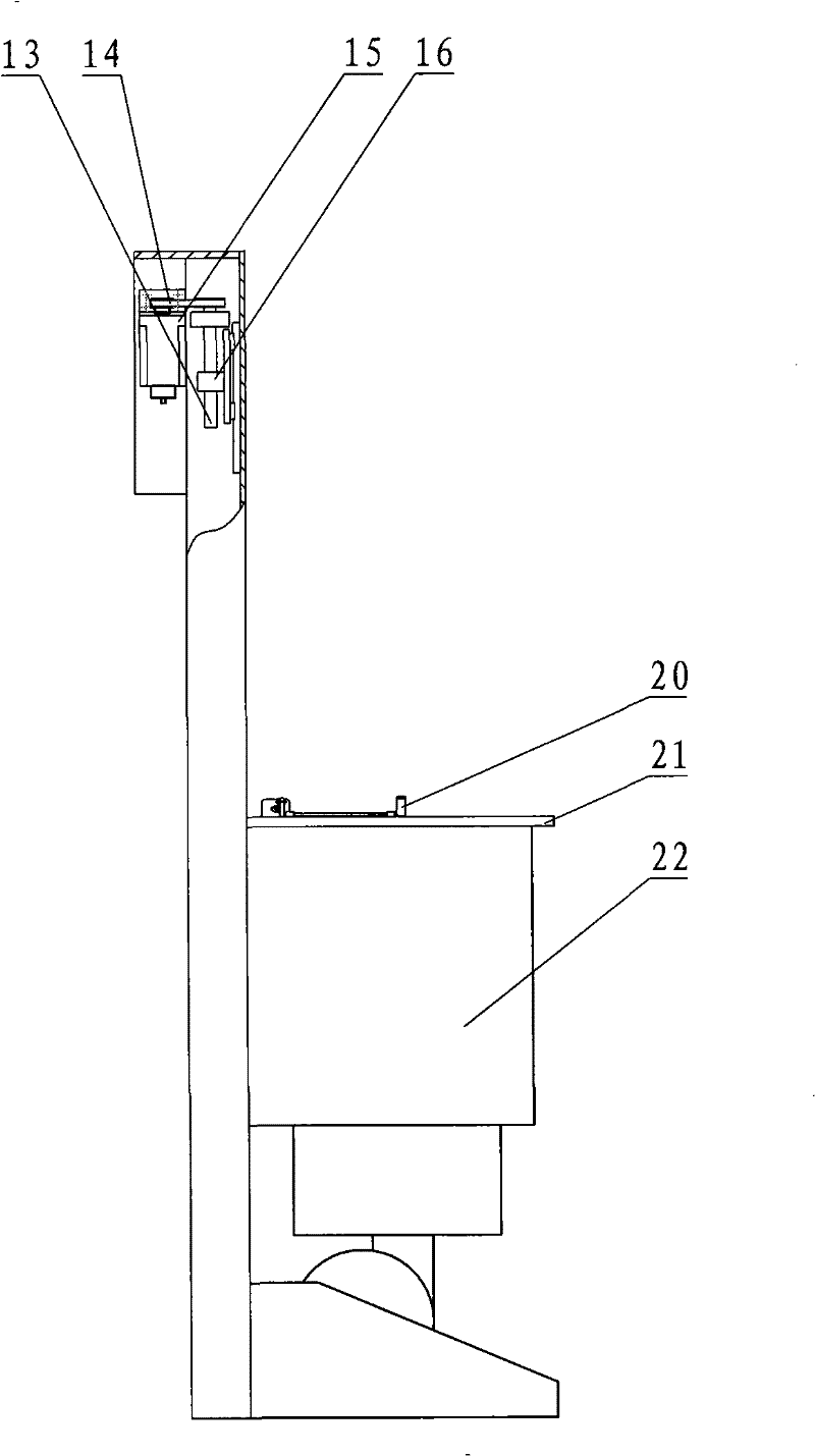
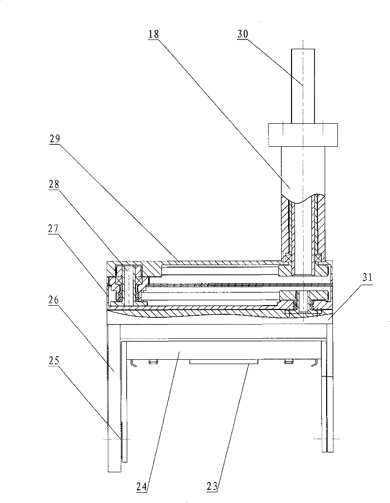
[0035] according to Figures 1 to 10 The specific structure of this invention is demonstrated in detail. The flip-type wafer automatic transfer device is based on inheriting the advantages of patented technologies such as "a method of delivering wafers for IC manufacturing process" in US Patent 6,086,323, and is redesigned according to the defects existing in the prior art. It includes a frame 1, a loading platform 21 fixed on the frame 1, a bellows body 22 with a claw mechanism 20 assembled on the frame 1 for lifting and moving, and a bellows body 22 with a grasping mechanism 20 for lifting and extending movement. The arm mechanism 19 of the mechanism 24 and the like. The bellows body 22 is an integrated air filtration system, which can provide a clean micro-environment. Its working principle is basically the same as the method in the above-mentioned US patent technology, and will not be repeated here.

[0036] like figure 1 , 2 As shown, the bellows body 22 is assembled...


PUM


Abstract

A compact wafer automatic transfer device, which overcomes the shortcomings of the existing technology that it cannot perform complex actions in the narrow space of the process, including the rack, loading platform, bellows body and arm mechanism. The technical points are: arm mechanism The lifting and stretching motors are not on the same plane. The lower arm is connected to the grasping mechanism through the translation mechanism and the turning mechanism, and the gear linkage transmission mechanism is used to drive the grasping mechanism to rotate around the axis. The grasping motor of the grasping mechanism drives the jaws to reciprocate. , The positioning mechanism on the grabbing mechanism is provided with an adjustable positioning block. Its design is reasonable, the transfer between processes runs smoothly, and the action is flexible and reliable. While completing the automatic transfer of wafers in the horizontal or vertical state within the limited travel space, it can also realize the left and right translation and flipping of the wafer cassette to adapt to the process equipment set up side by side. Automatic transmission is fully realized in a narrow space where the center distance is smaller than the center distance of the transmission equipment, and it can be flexibly stopped when encountering external interference to achieve a precisely controlled transmission effect.

Description

technical field [0001] The present invention relates to a wafer conveying device. In particular, the structure design for loading and unloading the standard mechanical interface (Standard Mechanical Interface, SMIF) wafer cassette is more compact, and its overall height is significantly reduced, leaving more space for the process equipment in the limited travel space. A compact wafer automatic transfer device that further expands the scope of application. Background technique [0002] Currently, wafer handling is critical to IC manufacturing during semiconductor manufacturing. In order to ensure the quality of the wafers during transportation between different processes and avoid the wafers from being contaminated by dust particles or other contamination, more and more transportation work uses standard transportation containers, that is, the standard mechanical interface (standard mechanical interface, referred to as SMIF) is used. )technology. For example, in US Pat. Nos...

Claims


Application Information

Patent Timeline
Patent Type & Authority Patents(China)
IPC IPC(8): H01L21/677
Inventor 吴功
Owner SHANGHAI FORTREND TECH CO LTD
Why Eureka
Try Eureka