Axial piston machine having a hydrostatic support of the hold-down

A technology of an axial plunger machine and a pressing device, which is applied in the field of axial plunger machines

Inactive Publication Date: 2009-06-17
HYDROMATIK GMBH
View PDF2 Cites 10 Cited by
  • Summary
  • Abstract
  • Description
  • Claims
  • Application Information

AI Technical Summary

Problems solved by technology

[0004] The known axial piston machines have the disadvantage that the carriage is essentially compressed by a common pressure plate with mechanical pretension independently of the choice of its shape

Method used


Image

  • Axial piston machine having a hydrostatic support of the hold-down
  • Axial piston machine having a hydrostatic support of the hold-down
  • Axial piston machine having a hydrostatic support of the hold-down

Examples


Embodiment Construction

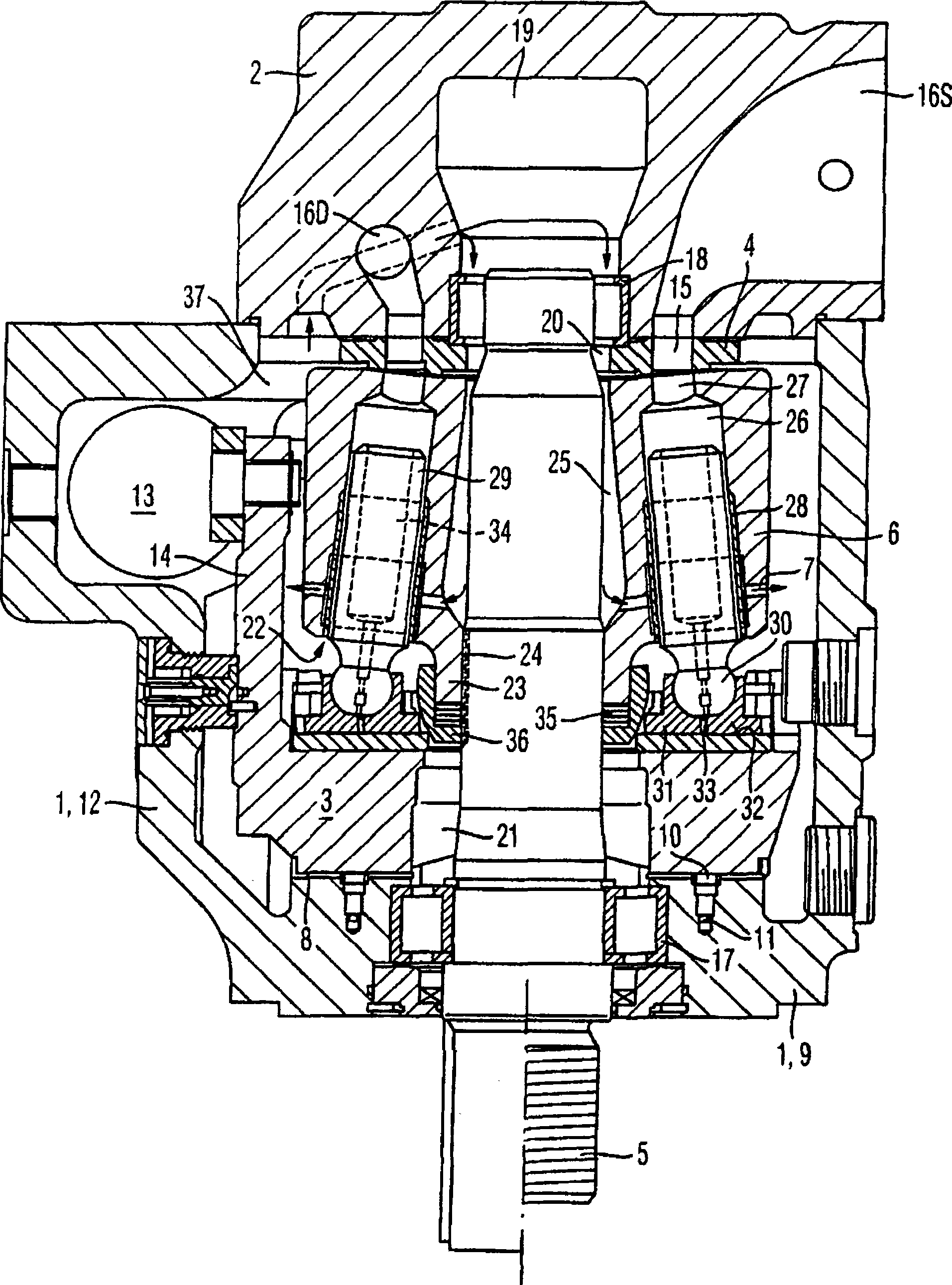
[0012] For a better understanding of the measures according to the invention, figure 1 Firstly, an axial piston machine of swash plate design according to the prior art is shown in section in a sectional view with adjustable working capacity and flow direction. Axial piston machines comprise the following as main components in a known manner: with figure 1 Hollow cylindrical shell 1 at the open end of the upper end face, connecting plate 2 fixed on the shell 1 to close its open end, disc cam or swash plate 3, control body 4, main shaft 5, hydraulic cylinder block 6. Furthermore, a cooling circuit 7 is provided in this exemplary embodiment.

[0013] The swash plate 3 is formed as a so-called slewing frame with a semi-cylindrical cross section and is supported on two correspondingly shaped bearing shells 8 under static pressure relief by means of two bearing surfaces spaced apart from one another and running parallel to the direction of rotation. , The bearing bush is fixed on...


PUM


Abstract

An axial piston machine comprises a housing (1) which receives an eccentric disc (3) and a rotatably mounted cylinder drum (6) having cylinders (26, 28) and pistons (29) which can move to and fro in the former and the ends of which which protrude out of the cylinders (26, 28) are supported on the eccentric disc (3) via a sliding face (31) of a sliding disc (32), and also comprises a hold-down (36), by which the sliding face (31) is held in contact with the sliding disc (32). A pressure which prevails in a pressure space (40) under the sliding shoes (31) compensates partially for a pressure which is exerted on the sliding shoe (32) by the hold-down (36), via a connecting restrictor (43).

Description

technical field [0001] The invention relates to an axial piston machine according to the preamble of claim 1 . Background technique [0002] For example, DE 44 23 023 A1 discloses an axial piston machine with a housing, the inner space of which includes a leakage chamber and accommodates disc cams and rotatably supported hydraulic cylinders and hydraulic cylinders and reciprocating in the hydraulic cylinders. A moving plunger, the end of which protrudes from the hydraulic cylinder is supported on a disc cam. [0003] Furthermore, DE 196 01 721 A1 discloses a weight-optimized multi-part slide for slidingly mounting the plungers of an axial or radial plunger machine, such as a sliding surface formed, for example, on a swash plate. The slide comprises a support body connected to the associated plunger and a slide on the sliding surface. The carriage is constructed of materials that reduce the weight of the carriage, thereby reducing the centrifugal force acting on the carriag...

Claims


Application Information

Patent Timeline
Patent Type & Authority Applications(China)
IPC IPC(8): F04B1/12F01B3/00F03C1/06
CPCF03C1/0605F04B1/124F01B3/0085F01B3/00F04B1/12
Inventor 赖纳·施托尔策
Owner HYDROMATIK GMBH
Why Eureka
Try Eureka