
Accessory mounting structure

A technology of auxiliary equipment and installation structure, which is applied in the direction of mechanical equipment, engine components, machines/engines, etc., and can solve problems such as difficult alternator maintenance, reduced bolt hole accuracy, and inability to maintain alternator pulley coplanarity, etc. Achieve the effect of easy positioning, convenient positioning and fixed work, and stable maintenance

Active Publication Date: 2009-06-24
MITSUBISHI MOTORS CORP
View PDF2 Cites 5 Cited by
  • Summary
  • Abstract
  • Description
  • Claims
  • Application Information

AI Technical Summary

Problems solved by technology

[0008] In addition, weight is added to the bolt holes where the alternator is fixed, and repeatedly inserting and removing bolts for replacement and maintenance of the alternator may reduce the accuracy of the bolt holes
As a result, it is difficult to maintain the alternator in a predetermined position with high precision, and there is a possibility that the pulley of the alternator and the pulley of the crank cannot be kept coplanar

Method used


Image

  • Accessory mounting structure
  • Accessory mounting structure
  • Accessory mounting structure

Examples


Embodiment Construction

[0027] The embodiments of the present invention will be explained in detail with reference to the drawings.

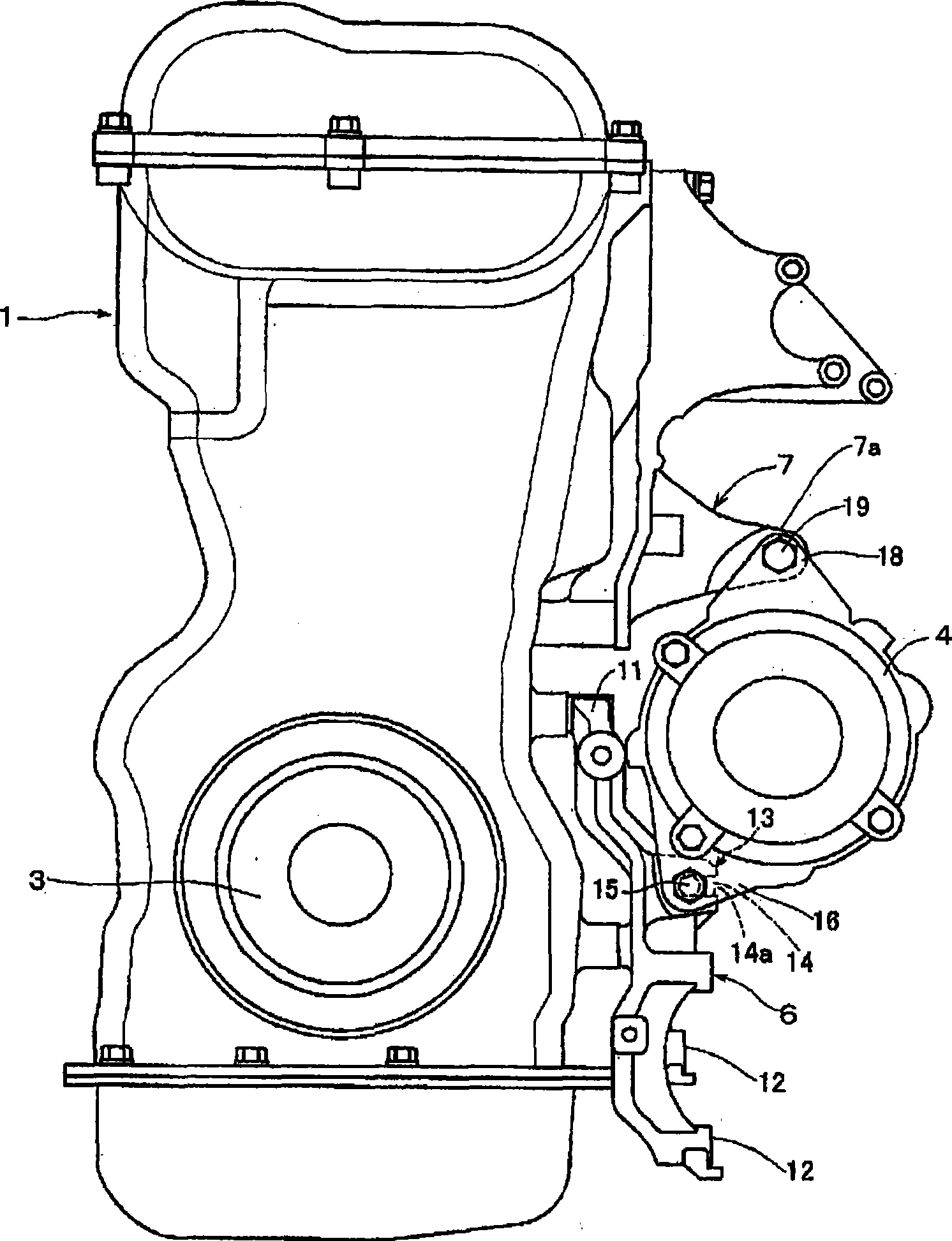
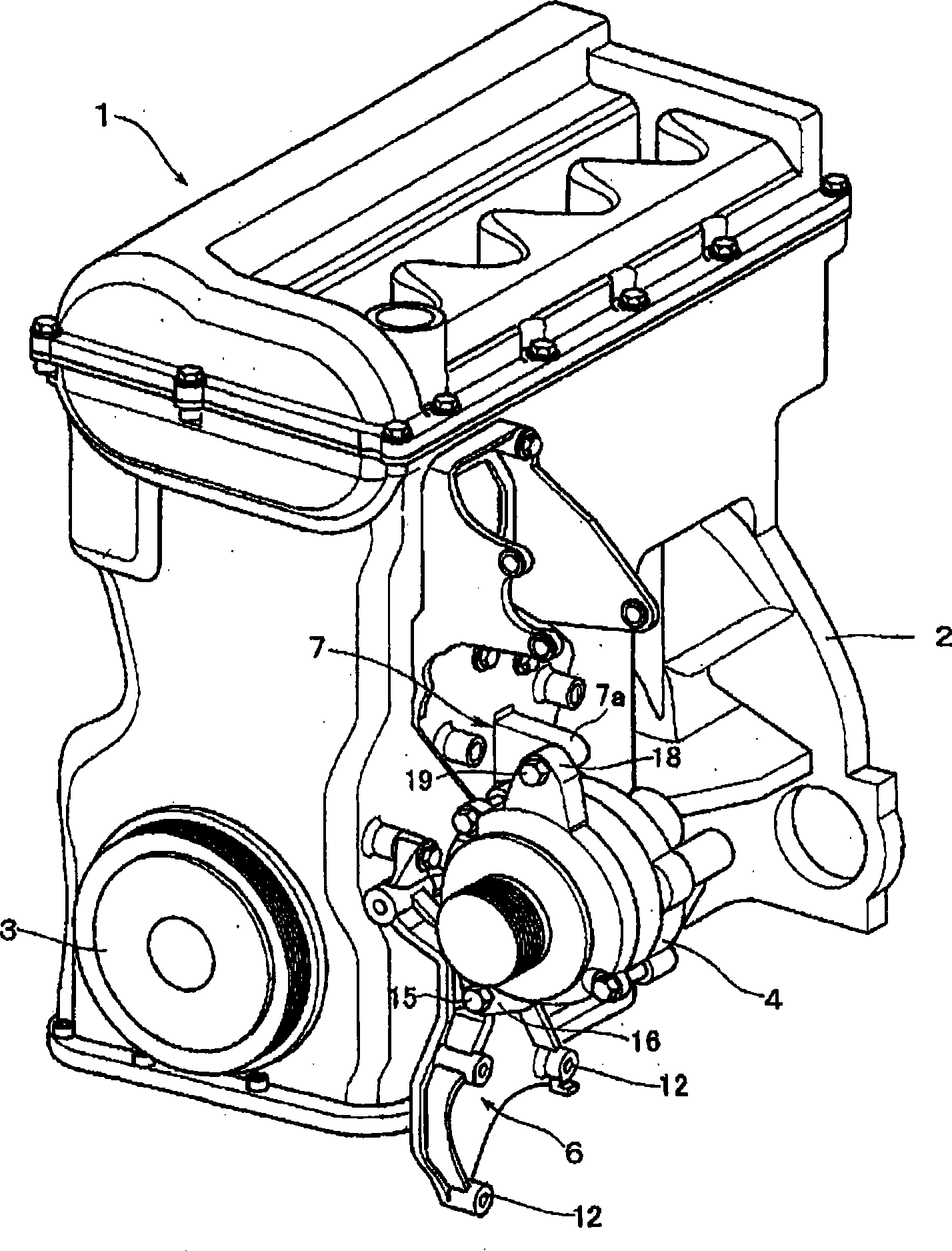
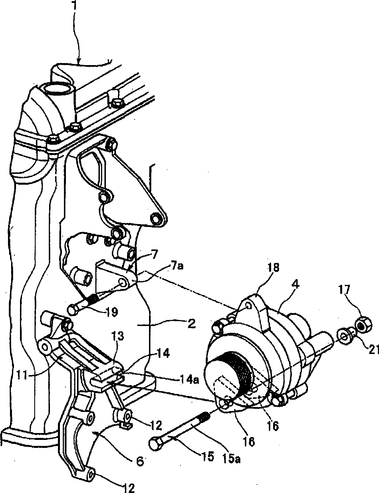
[0028] Such as figure 1 with 2 As shown, a vehicle engine (engine) 1 is an in-line multi-cylinder engine, and a crank pulley 3 connected to the crank is arranged on the front side of the cylinder block 2 of the engine 1. On the other hand, beside the side surface of the cylinder block 2, the alternator 4 as auxiliary equipment is held. In addition, the power steering pump and the air compressor are held beside the side surface of the cylinder block 2.

[0029] The pulley of auxiliary equipment such as the alternator 4 is arranged on the same plane as the crank pulley 3, and the belt is looped around the crank pulley 3 and the auxiliary equipment pulley through an idler pulley and a tension pulley. By doing so, the driving force of the crank of the engine 1 is transmitted to auxiliary equipment such as the alternator 4.

[0030] Such as Figure 1 to 5 As shown, an alternat...


PUM


Abstract

A horizontal groove extending horizontally when an alternator bracket is fixed to a cylinder block of a vehicle engine is formed in the alternator bracket. A shank of a bolt inserted through mounting pieces of an alternator is inserted into the horizontal groove from a horizontally lateral direction toward the cylinder block to support the bolt on a lower surface of the horizontal groove. After insertion, the bolt is restrained from moving toward an opening of the horizontal groove. Since the insertion of the bolt into the horizontal groove is facilitated, and the weight of the alternator is borne by the lower surface of the horizontal groove, a burden on a fixing portion is reduced, and it becomes easy to position the alternator and hold it when it is fixed. Thus, the accessory can be mounted on the cylinder block with satisfactory work efficiency and with support accuracy kept high.

Description

[0001] The entire disclosure of Japanese Patent Application No. 2007-329144, filed on December 20, 2007, is expressly incorporated herein by reference. Technical field [0002] The present invention relates to a mounting structure for accessory equipment installed on a vehicle engine. Background technique [0003] The vehicle engine is equipped with auxiliary equipment such as an alternator, a power steering pump, and an air compressor. These auxiliary equipment are driven by the rotational force of the crank of the vehicle engine transmitted through a V-ribbed belt or V-grooved belt, pulleys, etc. Therefore, the auxiliary equipment is positioned and held on the cylinder block of the vehicle engine so that the crank pulley and the auxiliary equipment pulley are kept in the same plane. [0004] Auxiliary equipment such as an alternator is held on the cylinder block of the vehicle engine through an auxiliary equipment mounting bracket. That is, the auxiliary equipment mounting brack...

Claims


Application Information

Patent Timeline
Patent Type & Authority Applications(China)
IPC IPC(8): F02B67/00
CPCF02B67/00F02F7/0068F02B67/06F02B67/04
Inventor 小山和明堀澄人松井知史
Owner MITSUBISHI MOTORS CORP
Learn More