Siphon type gas-liquid separation and oil return apparatus in parallel compression refrigeration units

A technology of compression refrigeration and gas-liquid separation, applied in the direction of refrigerators, refrigeration components, refrigeration and liquefaction, etc., can solve the problems of complex structural design of the overall unit, affect the structural design of the overall unit, reduce the amount of liquid absorption, etc., and achieve improved system operation Efficiency and compressor reliability, simple and reasonable structure, and the effect of reducing pressure

Inactive Publication Date: 2009-06-24
李世岗
View PDF0 Cites 11 Cited by
  • Summary
  • Abstract
  • Description
  • Claims
  • Application Information

AI Technical Summary

Problems solved by technology

With an independent gas-liquid separator, all the gas returned from the evaporator first flows through an independent standard gas-liquid separator, and then enters the suction header after being separated. The compressor suction branch pipes of each compressor are drawn from the suction header. The device system has one more component, and the air pressure is strong, which affects the structural design of the overall unit and increases the cost; there is no independent gas-liquid separator, the return gas directly flows into the suction header, and the compressor suction branch pipe is inserted into the suction header. At the bottom of the pipe, the compressor has a large liquid suction volume, so the compressor must be raised above the suction header to reduce the liquid suction volume, which makes the structural design of the overall unit complex

Method used


Image

  • Siphon type gas-liquid separation and oil return apparatus in parallel compression refrigeration units

Examples


Embodiment Construction

[0009] The present invention will be further described below in conjunction with embodiment.

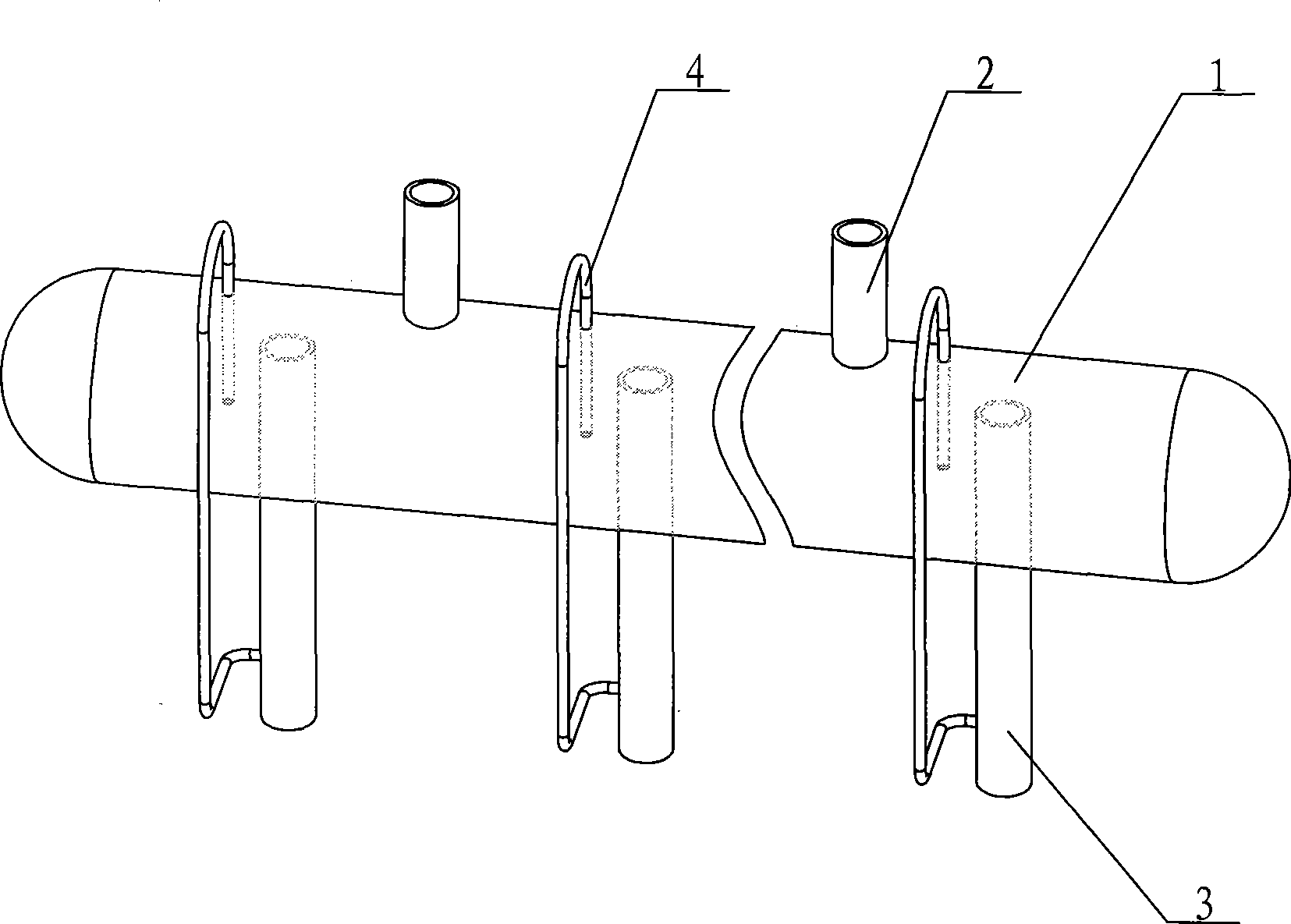
[0010] figure 1 A siphon type gas-liquid separation and oil return device in a parallel compression refrigeration unit, the evaporator return pipe 2 is installed on the top of the suction header 1, and the suction port section of the compressor suction branch pipe 3 passes through the suction header The bottom of 1 is inserted into the middle or above the middle of the suction manifold 1, one end of the siphon oil return pipe 4 is connected to the air outlet section of the compressor suction branch 3, and the other end is inserted from the top of the suction manifold 1 to the suction manifold 1 At or below the middle of the tube.

[0011] The entire parallel compression refrigeration unit mainly includes four major components: compressor, condenser, evaporator and expansion valve, among which the suction header has a special structure. The refrigerant gas is compressed by the compr...


PUM


Abstract

The invention relates to a siphon gas-liquid separation and oil return device in a parallel compression refrigeration unit. The siphon gas-liquid separation and oil return device comprises an air suction header, an air return pipe of an evaporator and an air suction branch pipe of a compressor, the air return pipe of the evaporator is arranged at the top part of the air suction header, the air suction header is connected with an air suction port of the compressor by the air suction branch pipe of the compressor, the air suction branch pipe of the compressor is extended into the middle part or the position above the middle part of an inner cavity of the air suction header from the bottom part of the air suction header, one end of a siphon oil return pipe is connected with the air suction branch pipe of the compressor, and the other end is extended into the middle part of the position below the middle part of the inner cavity of the air suction header from the top part of the air suction header. The device has simple structure and convenient processing, and the pressure of an airflow pipeline is reduced by improving the height of the air suction branch pipe of the compressor inserted in the air suction header; the device adopts the thinner siphon oil return pipe for absorbing oil liquid, thereby effectively controlling the liquid absorption of the compressor, further improving the operation efficiency of a system and the reliability of the compressor and enhancing the product performance.

Description

technical field [0001] The invention relates to a parallel compression refrigeration unit, in particular to a siphon type gas-liquid separation and oil return device in a multi-head parallel compression refrigeration unit. Background technique [0002] In the multi-head parallel compression refrigeration unit, the suction branch pipes of multiple compressors are connected to a suction header. The gas from the evaporator to the suction header often brings out some liquid. If the gas and liquid are not combined Separate and control the amount of liquid suction, the suction of a large amount of liquid will have a strong hydraulic impact on the compression parts of the compressor, and dilute the lubricating oil, resulting in damage to the compressor. While the gas-liquid is separated, it is also necessary to ensure that the lubricating oil coming back along the suction pipe can be continuously brought back to the compressor with the gas, otherwise the compressor will eventually ...

Claims


Application Information

Patent Timeline
Patent Type & Authority Applications(China)
IPC IPC(8): F25B43/02
Inventor 李世岗
Owner 李世岗
Why Eureka
Try Eureka