
Measuring method and apparatus for accurately transmitting ground bench level to overhead viaduct

A measurement method and technology of benchmarking points, which are applied in measurement devices, height/level measurement, mapping and navigation, etc., can solve the problems of high prism of instruments, inconvenient measurement, harsh observation conditions, etc., and meet the requirements of easy operation and observation conditions. Loose, precise effects

Inactive Publication Date: 2009-06-24
成都十九号极速文化传播股份有限公司
View PDF1 Cites 7 Cited by
  • Summary
  • Abstract
  • Description
  • Claims
  • Application Information

AI Technical Summary

Problems solved by technology

This traditional method is called "triangular elevation measurement" method. This method needs to manually measure the height of the instrument and the height of the prism, and it needs to be limited to a short distance. The measurement is inconvenient and the accuracy is poor.
Another method is to set up a steel pipe frame on the viaduct, hang the authenticated steel ruler with millimeter markings and hang the weight to the ground, and set up optical levels with micrometers on the ground and bridge deck after standing still Observe the steel ruler to obtain the elevation difference. This method has harsh observation conditions. Although it can solve the problem, it cannot meet the requirements of quickness and simplicity.

Method used

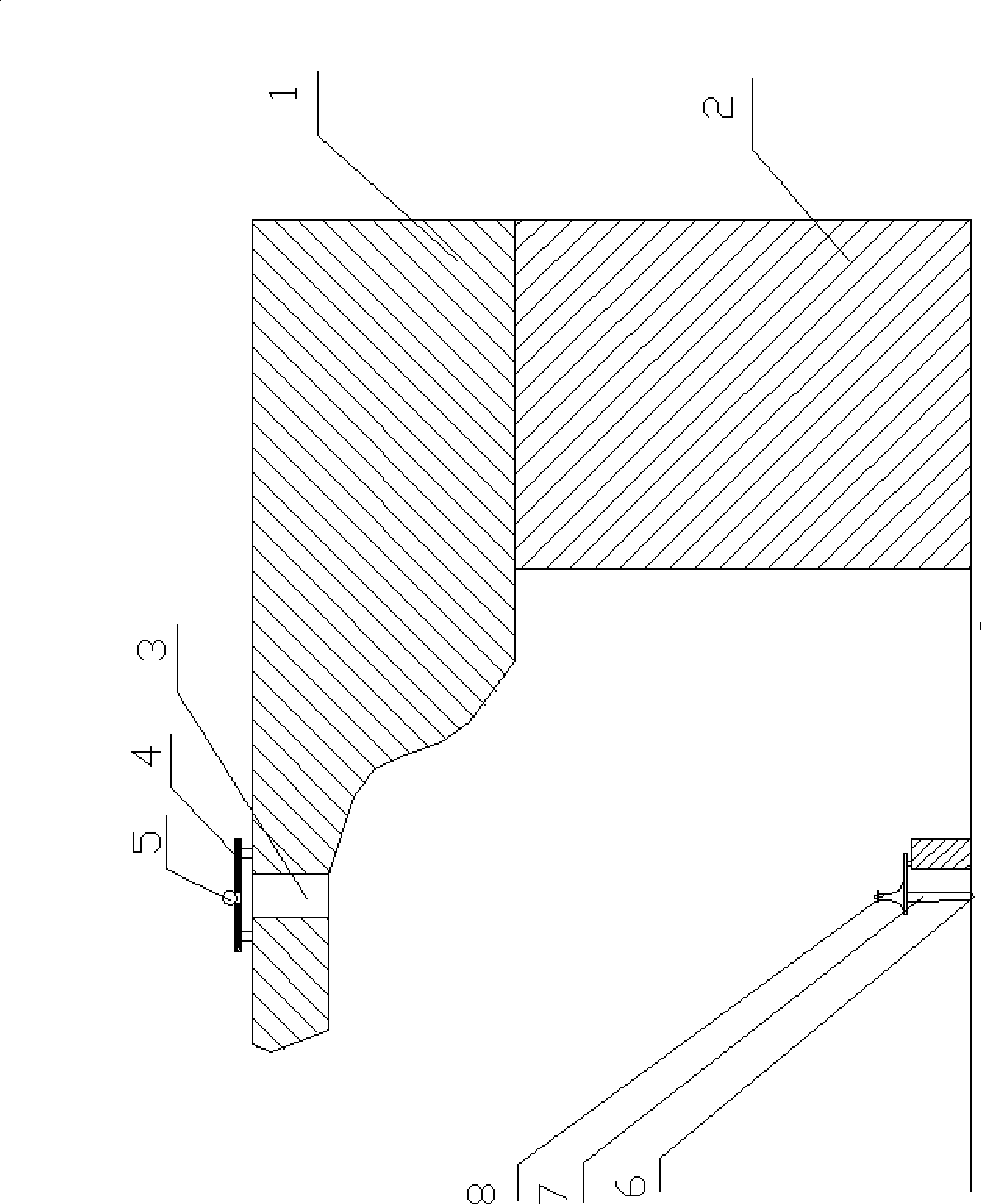

Image

  • Measuring method and apparatus for accurately transmitting ground bench level to overhead viaduct
  • Measuring method and apparatus for accurately transmitting ground bench level to overhead viaduct
  • Measuring method and apparatus for accurately transmitting ground bench level to overhead viaduct

Examples


Embodiment Construction

[0018] Such as figure 1 As shown, the box girder 1 between the two piers 2 on the viaduct has reserved a plurality of drainage holes 3, and a flat plate 4 is processed according to the diameter of the drainage hole or the beam gap between the two box girders 1, and the center of the flat plate is opened. A through hole is used to place the spherical measuring prism 5, the radius of the through hole is smaller than the radius of the spherical measuring prism, and the radius of the through hole is larger than the radius of the reflecting surface of the spherical measuring prism.

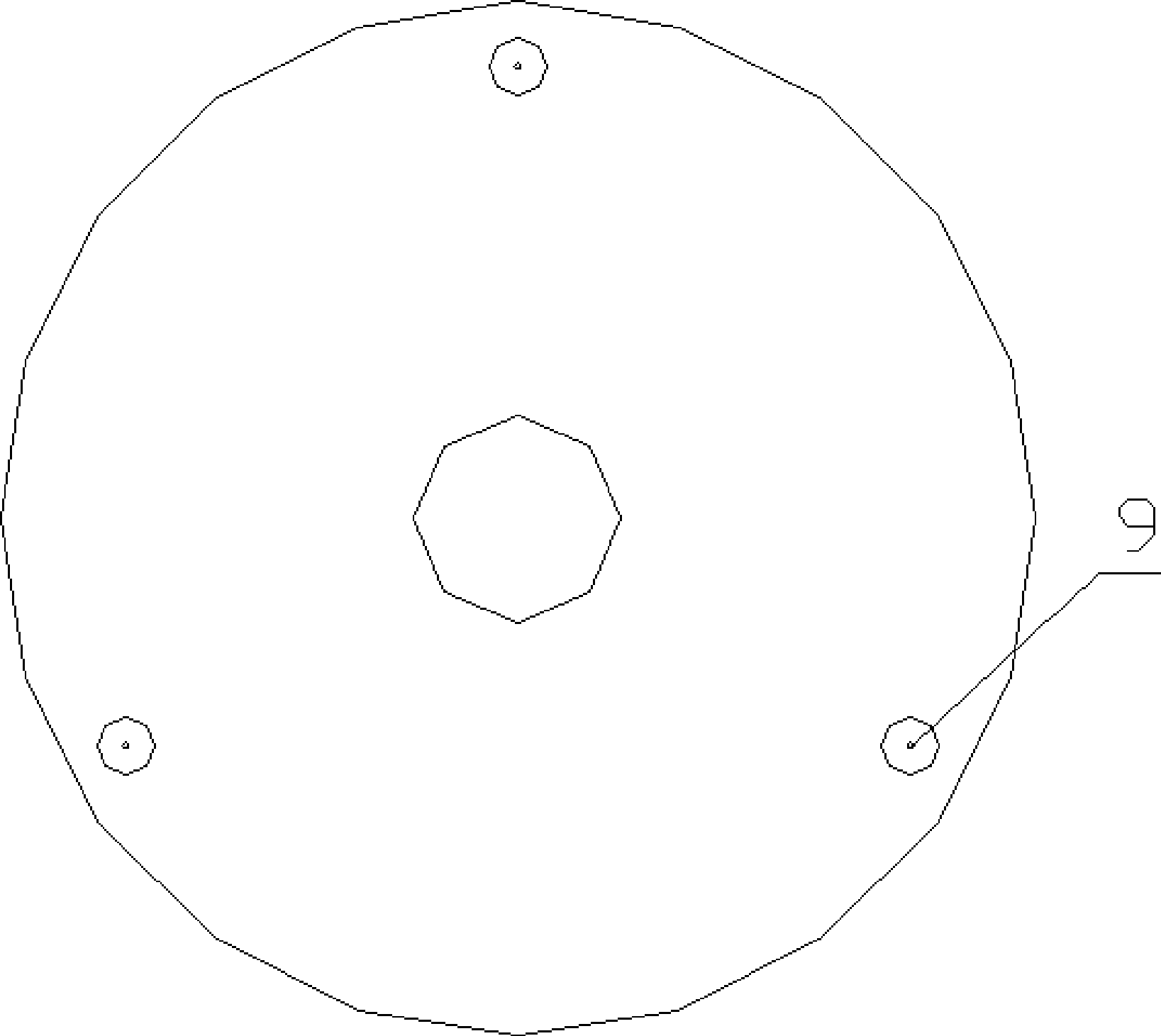
[0019] Such as figure 2 and image 3 As shown, the above-mentioned flat plate 4 is preferably a metal circular flat plate, on which three landing points 9 are arranged at equal angles, and the three landing points 9 can determine a unique plane. The above-mentioned spherical measuring prism 5 can adopt the spherical measuring prism with application number 2008103046073.

[0020] Pre-buried a measur...


PUM


Abstract

The invention provides a measurement method for accurately transmitting the ground bench level onto a high-level bridge. The measurement method comprises the following steps: 1) projecting the centers of the effective aperture or the space of drain holes or beam crevices to the ground, pre-burying a measuring nail thereon, and gravitationally measuring the level thereof from the bench of a known level through a level gauge; 2) mounting a diagonal eyepiece on the eyepiece of a total station instrument, and rotating the total station telescope to the vertical direction; 3) placing a flat plate on the drain holes or the beam crevices, and placing a measuring prism on the circular hole of the flat plate; 4) ranging the center of the measuring prism, and acquiring the average value of qualified observed values for a plurality of times; 5) observing the difference in height from the vertex of the measuring prism to the CPIII point at the top end of a bump wall; and 6) processing data to acquire the level HCPIII of the CPIII point at the top end of the bump wall. The invention has the advantages that the difficult problem in directly transmitting the bench level to the viaduct can be solved; the accuracy is high; the requirement for observation conditions is low; and the operation is easy.

Description

technical field [0001] The invention relates to a method for measuring and locating a level point on a viaduct, in particular to a method and a device for accurately transmitting the elevation of a level point on the ground to the viaduct. Background technique [0002] my country has adopted a large number of bridge structures in the construction of high-speed railways, and some bridges are tens of kilometers long. In order to ensure the high-precision requirements of high-speed railway construction, precise construction is required on these super-large bridges, tunnels, and roadbeds. Control network, also known as CPIII network. The CPIII network is composed of a pair of CPIII points distributed on both sides of the line about 60m apart. Each CPIII point needs to measure the precise plane coordinates and elevation. However, the benchmarks with known elevations are all set on the ground. The accurate transmission of the benchmarking point elevation to the CPIII point located...

Claims


Application Information

Patent Timeline
IPC IPC(8): G01C5/00
Inventor 陈心一周敬勇姚云峰杜鹃罗小军杨娱唐杰彭兵蒋书姜燮荣张晓燕
Owner 成都十九号极速文化传播股份有限公司
Learn More