Nondestructive sheet material bending mould

A technology for bending molds and plates, which is applied in the field of mechanical processing, and can solve problems such as difficult guarantees, unevenness, and coarse tissue

Inactive Publication Date: 2009-07-01
NO 510 INST THE FIFTH RES INST OFCHINA AEROSPAE SCI & TECH
View PDF0 Cites 13 Cited by
  • Summary
  • Abstract
  • Description
  • Claims
  • Application Information

AI Technical Summary

Problems solved by technology

It is difficult to guarantee the general bending method, so we invented the mold through practice
[0003] Bending damage analysis: when general equipment bends thick plates (mainly for non-ferrous metal plates), due to the high speed of mechanical equipment bending, the material may follow up in time during the bending process. After the material is bent, the material thickness of the bent part is easily damaged. Thinning or internal tissue is pulled to cause the tissue to be thick and uneven

Method used


Image

  • Nondestructive sheet material bending mould

Examples


Embodiment

[0016] Bottle holder processing

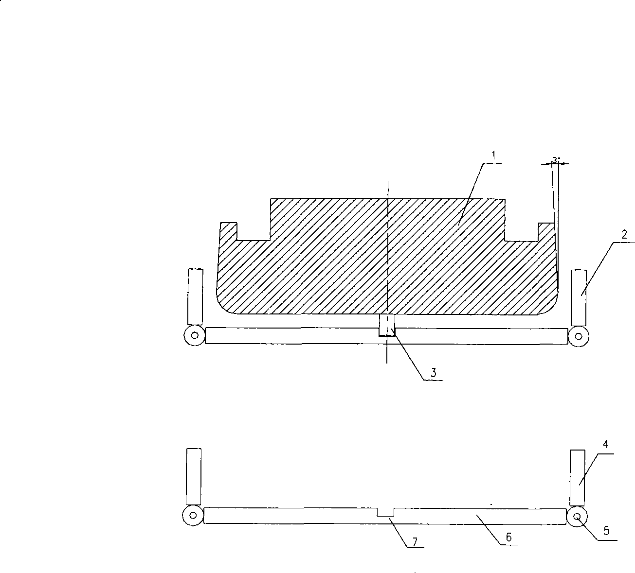
[0017] 1. The material of the bracket is LF12, the thickness is 5mm, the bending angle is 90°, and the area is 400×200mm 2 , place the plate. Place the plate to be processed on the lower die 2. Note that the grain direction of the material should be vertical to the bending line.

[0018] 2. Align the upper mold 1 to press the plate, and then fix the upper mold 1, the plate and the lower mold 2 with the pin 3, so as to prevent the plate to be processed from moving.

[0019] 3. Use a special jack to act on the outside of the two bending plates 4 to control the moving speed, requiring a uniform and slow speed until the plate reaches the two ends of the upper mold 1. Since the two ends of the upper mold 1 are set at 87°, Use 3° as the bending rebound to ensure that the bend is in place at 90° at one time, avoiding back-and-forth correction.

[0020] 4. The shape of the finished bracket is U-shaped, and the bottom end is perpendicular to the two ...


PUM

PropertyMeasurementUnit
thicknessaaaaaaaaaa

Abstract

The invention relates to a mould, in particular to an undamaged plate bending mould, and belongs to the field of mechanical processing. The mould mainly comprises an upper mould, a lower mould and a pin bolt; the lower mould consists of a bending plate, an axle pin, a lower soleplate, and a positioning hole. The upper mould is convex; the lower mould is concave; and the shapes of the upper mould and the lower mould are boat-shaped. The undamaged plate bending mould does not cause damage or larger damage to a bended plate and can shape the palate once by bending the plate.

Description

technical field [0001] The invention relates to a mold, in particular to a non-destructive plate bending mold, which belongs to the field of mechanical processing. Background technique [0002] In the processing of some mechanical parts, there are often parts that are bent and formed from the plate, especially when the bent plate is used as a load-bearing part, it is necessary to ensure both the bending accuracy and the strength of the bent part. It is difficult to guarantee the general bending method, so we invented the mold through practice. [0003] Bending damage analysis: when general equipment bends thick plates (mainly for non-ferrous metal plates), due to the high speed of mechanical equipment bending, the material may follow up in time during the bending process. After the material is bent, the material thickness of the bent part is easily damaged. Thinning or internal tissue is pulled to cause the tissue to be thick and uneven. When the bent local tissue is coole...

Claims


Application Information

Patent Timeline
Patent Type & Authority Applications(China)
IPC IPC(8): B21D37/10B21D5/00
Inventor 陈正刚林志刚潘雁平
Owner NO 510 INST THE FIFTH RES INST OFCHINA AEROSPAE SCI & TECH
Why Eureka
Try Eureka