Top pushing mechanism of steel box girder of single longitudinal clapboard on wide bridge deck and top pushing method

A technology of steel box girders and medial diaphragms, which is applied in bridges, bridge construction, erection/assembly of bridges, etc., can solve the problem that it is difficult to ensure that the steel box girders are well stressed and the alignment of the bridge can not meet the requirements of the bridge design, and affect the force of the steel box girders and other issues, to achieve the effect of simplifying construction, saving costs, and clear force

Active Publication Date: 2010-11-24
THE FIRST CIVIL ENG CO LTD OF CREC SHANGHAI GRP
View PDF6 Cites 6 Cited by
  • Summary
  • Abstract
  • Description
  • Claims
  • Application Information

AI Technical Summary

Problems solved by technology

However, in some steel box girder jacking constructions, the steel box girder is designed as a single longitudinal diaphragm and there is a vertical curve in the bridge. , which will not only affect the stress of the steel box girder, increase the construction cost, but also fail to meet the requirements of the designed bridge
[0004] For example, the Shuangyong Bridge in Liuzhou City, Guangxi, the steel box girder of the main ...

Method used


Image

  • Top pushing mechanism of steel box girder of single longitudinal clapboard on wide bridge deck and top pushing method
  • Top pushing mechanism of steel box girder of single longitudinal clapboard on wide bridge deck and top pushing method
  • Top pushing mechanism of steel box girder of single longitudinal clapboard on wide bridge deck and top pushing method

Examples


Embodiment Construction

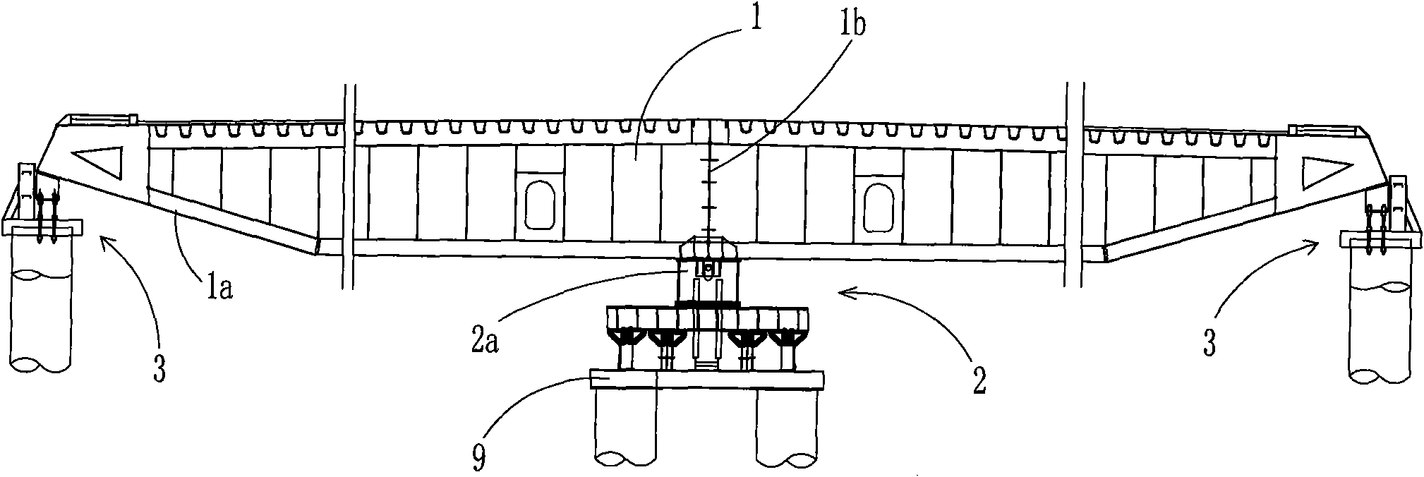
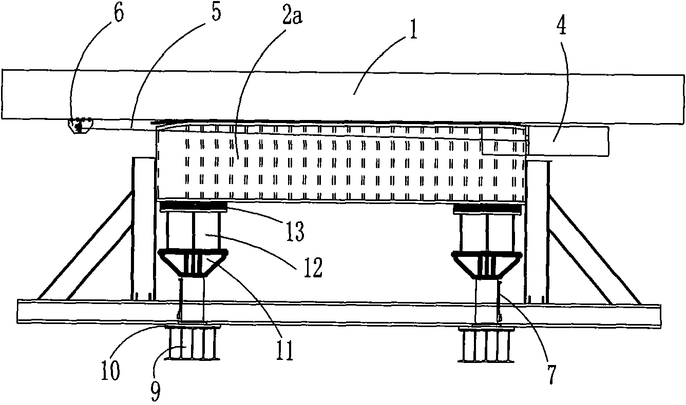
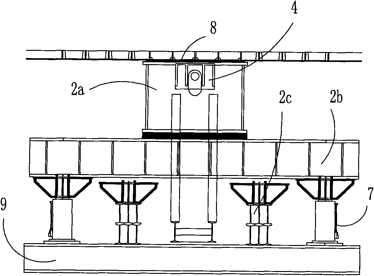
[0026] see figure 1 , figure 2 with image 3 , the pushing mechanism in this embodiment is composed of a main pushing mechanism 2 located in the center of the bottom of the steel box girder 1 and an auxiliary traction mechanism 3 respectively located at the ends of the lower inclined plates 1a of the steel box girder on both sides;

[0027] The main pushing mechanism 2 has a longitudinal main slideway 2a, which is located at the corresponding position of the central longitudinal diaphragm 1b of the steel box girder. The longitudinal main slideway 2a is supported on the central pier platform 2b, and the jacking jack 4 fixedly arranged on the central pier platform 2b, one end of the main traction cable 5 is connected to the jack 4, and the other end is connected to the tail of the steel box girder 1 of each segment through the anchor puller 6; on the central pier platform 2b The bottom is provided with a jacking jack 7 and a steel pier 2c that can be equipped with an adjustab...


PUM


Abstract

The invention discloses a top pushing mechanism of a steel box girder of a single longitudinal clapboard on a wide bridge deck and a top pushing method, which is characterized in that the top pushing mechanism comprises a main top pushing mechanism and two auxiliary traction mechanisms, wherein the two auxiliary traction mechanisms are respectively arranged in the lower bevel board ends of steel box girders at two sides; the main top pushing mechanism is provided with a longitudinal main slideway which is supported on a central buttress platform; a top pushing jack is fixedly arranged on the central buttress platform; one end of a main traction rope is connected to the top pushing jack and the other end thereof is connected to the tail end of each sectional steel box girder by an anchor-pulling device; the bottom of the central buttress platform is provided with a top lifting jack and a steel buttress which can be additionally provided with an adjusting cushion block and is used for adjusting the supporting height of the central buttress platform; and the auxiliary traction mechanisms are characterized in that two buttress platforms at the two sides are respectively provided with a lateral limit palate and a bottom auxiliary slideway corresponding to the lower bevel boards of the steel box girders at the two sides, and the end parts of the lower bevel boards at the two sides of the steel box girder are provided with the auxiliary traction ropes. The steel box girder of the invention has definite stress and can ensure top pushing quality of the steel box girder and cable shape of a bridge.

Description

technical field [0001] The invention relates to a jacking mechanism and a jacking method for a steel box girder with a wide bridge deck, and more specifically to a jacking mechanism and a jacking method for a steel box girder with a wide bridge deck during jacking construction. Background technique [0002] In the construction of steel bridges, the steel box girder is often constructed by multi-point continuous jacking, and the steel box girder is dragged by jacking jacks to finally complete the installation of the steel box girder. [0003] The current steel box girder jacking mechanism is set to more than two jacking slides according to the number of longitudinal diaphragms in the design section of the steel box girder, and there is no jacking limit device and vertical elevation adjustment device. However, in some steel box girder jacking constructions, the steel box girder is designed as a single longitudinal diaphragm and there is a vertical curve in the bridge. , which...

Claims


Application Information

Patent Timeline
IPC IPC(8): E01D21/00
Inventor 李飞唐俊杨慧丰伍军赵大昭冯海珍周运志李光均夏亚飞周立伟郑娟
Owner THE FIRST CIVIL ENG CO LTD OF CREC SHANGHAI GRP
Why Eureka
Try Eureka