Battery temperature control device of vehicle

A technology for managing device and battery temperature, which is applied in battery temperature control, power consumption devices, electric power devices, etc., and can solve problems such as deterioration of air conditioning efficiency and negative pressure in vehicle interior

Inactive Publication Date: 2009-07-01
CALSONIC KANSEI CORP
View PDF2 Cites 20 Cited by
  • Summary
  • Abstract
  • Description
  • Claims
  • Application Information

AI Technical Summary

Problems solved by technology

[0005] However, in the conventional invention, since the air passing through the battery is exhausted to the outside of the vehicle or to the luggage room, in this case, the air conditioning efficiency in the vehicle room always deteriorates, and the vehicle room becomes negative pressure.

Method used


Image

  • Battery temperature control device of vehicle
  • Battery temperature control device of vehicle
  • Battery temperature control device of vehicle

Examples


Embodiment 1

[0020] Next, Example 1 will be described.

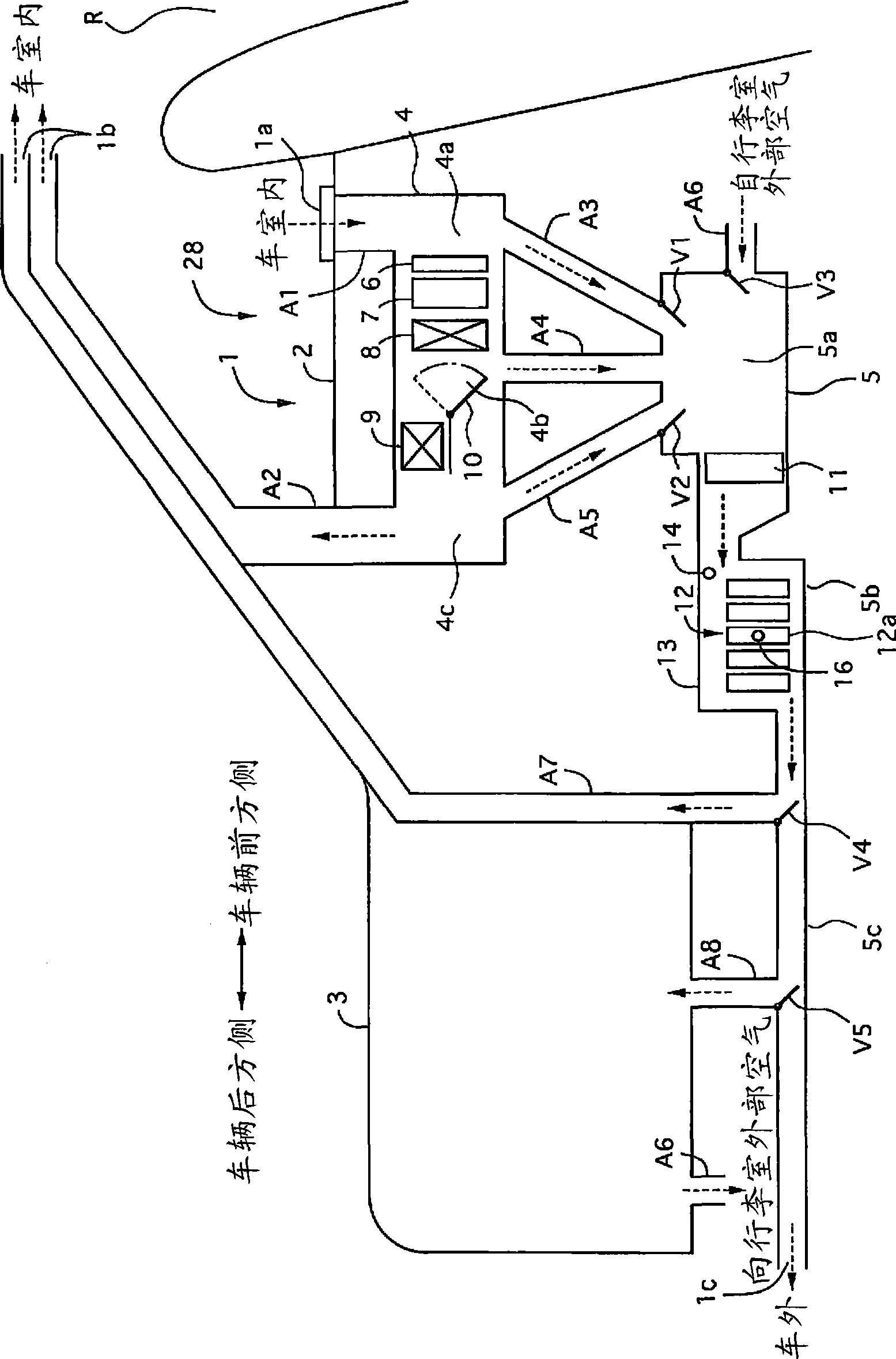
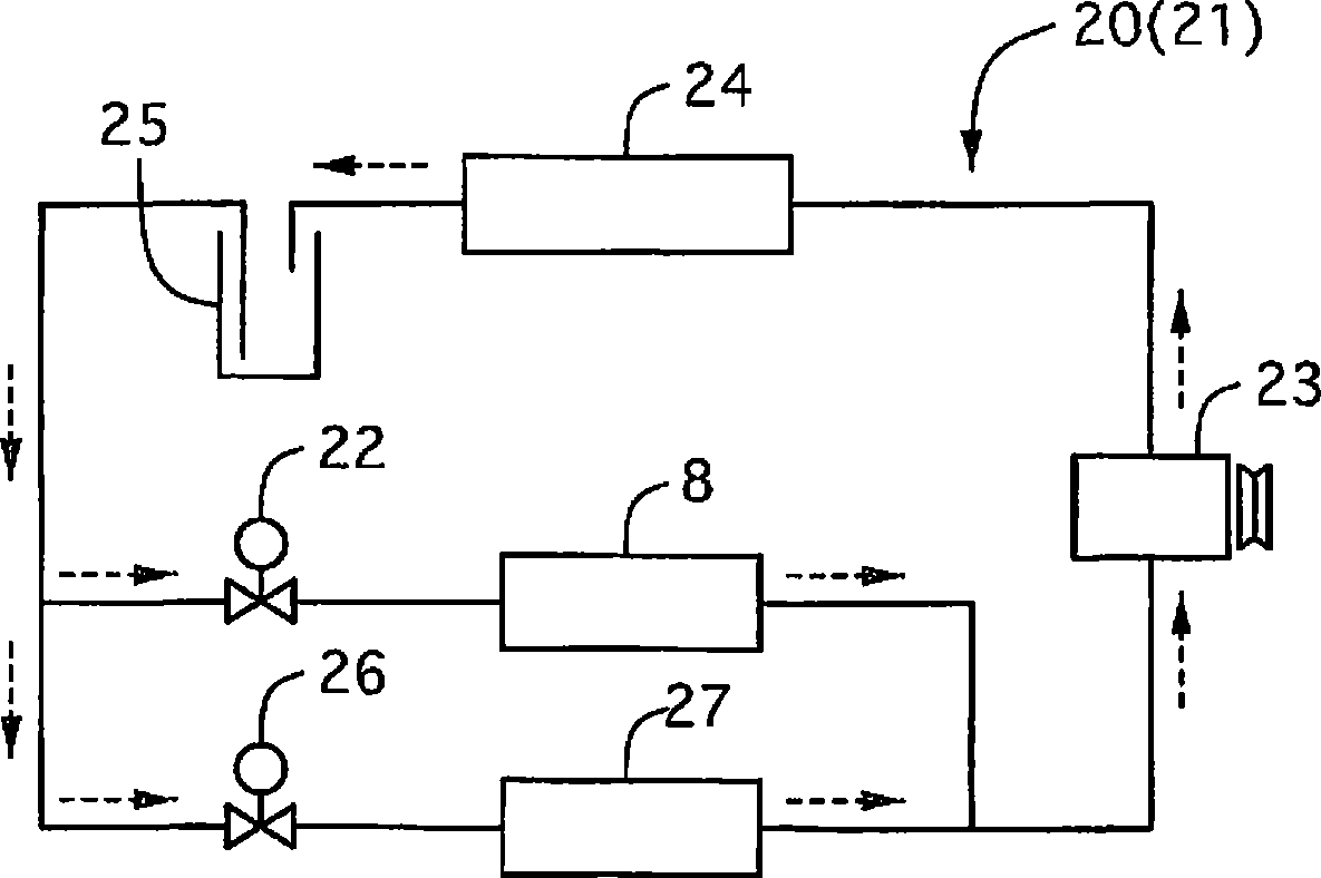
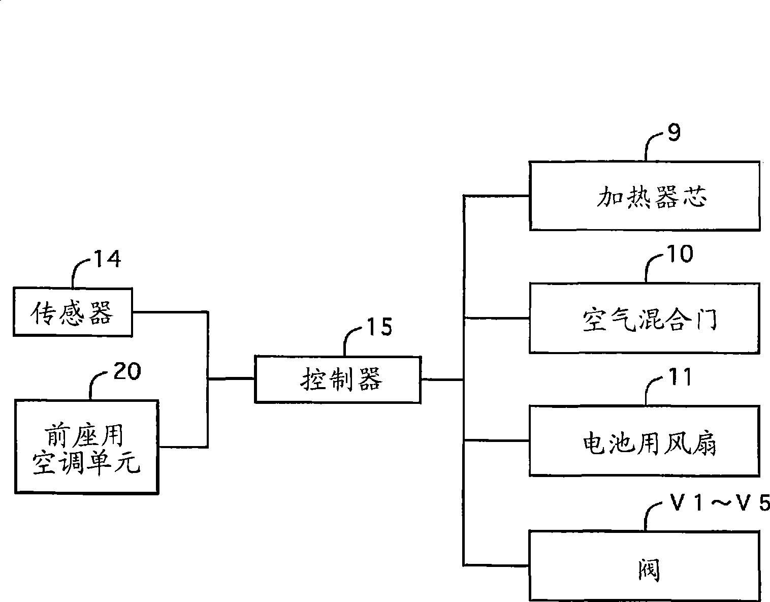
[0021] figure 1 is an overall view showing the battery temperature management device of Example 1, figure 2 It is a diagram showing the refrigeration cycle of the front seat air conditioning unit, image 3 It is the system structural diagram of embodiment 1, Figure 4 is a schematic diagram illustrating the temperature management of the battery of Example 1, Figure 5-8 It is a figure explaining the operation|movement of the temperature management of the battery of Example 1.

[0022] First, the overall structure will be described.

[0023] Such as figure 1 As shown, the battery temperature management device 1 of the embodiment includes a first case 4 disposed adjacent to the luggage room 3 directly under the rear portion 2 behind the rear seat in the vehicle compartment, and a first case 4 disposed on the first case 4. The second housing 5 below (corresponds to the compartment air introduction member of the technical solution...


PUM


Abstract

The invention provides a device for managing battery temperature. The invention can be used for allowing the air passing through a battery to come back to a vehicle chamber, thus preventing the air conditioner efficiency from being worsened and the subpressure in the vehicle chamber; wherein, the device for managing battery temperature is provided with a passage (A7) for the air passing through the battery (12) to come back to the vehicle chamber and a valve (V4); besides, when the temperature of the battery (12) reaches to the utmost temperature, the valve (V4) is closed, thus discharging the air passing through the battery to the outside of the vehicle through a discharging port (1c).

Description

technical field [0001] The invention relates to a battery temperature management device. Background technique [0002] Conventionally, a battery for supplying electric power to a running motor etc. is mounted in a hybrid vehicle or the like, and studies have been carried out to adopt a secondary battery such as a nickel-cadmium battery, a nickel-metal hydride battery, or a lithium battery that can be repeatedly charged and discharged as the battery. Battery. However, since the charging and discharging efficiency of this type of battery decreases at high temperatures, there is known technology for cooling the battery using cold air from a rear-seat air-conditioning unit (see Patent Documents 1 and 2). [0003] Patent Document 1: Japanese Patent Laid-Open No. 2004-1674 [0004] Patent Document 2: Japanese Patent Laid-Open No. 2007-185997 [0005] However, in the conventional invention, since the air passing through the battery is exhausted to the outside of the vehicle or t...

Claims


Application Information

Patent Timeline
Patent Type & Authority Applications(China)
IPC IPC(8): B60H1/00B60H1/22H01M10/50B60H1/24B60K1/04B60K11/06B60R16/04H01M10/60H01M10/613H01M10/615H01M10/625H01M10/633H01M10/6556H01M10/6563H01M10/663
CPCY02E60/12B60H1/00278H01M10/5004Y02T10/7005H01M10/5016B60L3/0046B60L11/1874H01M10/486H01M10/5067H01M10/5006Y02T90/16H01M10/5083H01M10/5022Y02T10/705B60H2001/003H01M10/5095B60L11/1875H01M10/625H01M10/615H01M10/633H01M10/663H01M10/6563H01M10/6571H01M10/613B60L58/26B60L58/27B60L58/18Y02T10/70Y02E60/10
Inventor 谷中拓弥
Owner CALSONIC KANSEI CORP
Why Eureka
Try Eureka