
Ceiling illuminating apparatus of elevator

A technology for lighting devices and ceilings, which is applied in the directions of lighting devices, lighting devices, components of lighting devices, etc.

Inactive Publication Date: 2013-01-16
TOSHIBA ELEVATOR KK
View PDF8 Cites 0 Cited by
  • Summary
  • Abstract
  • Description
  • Claims
  • Application Information

AI Technical Summary

Problems solved by technology

Such work takes a lot of work time and makes the elevator stop for a long time during this period, which is very inconvenient for the user.

Method used


Image

  • Ceiling illuminating apparatus of elevator
  • Ceiling illuminating apparatus of elevator
  • Ceiling illuminating apparatus of elevator

Examples


no. 1 approach

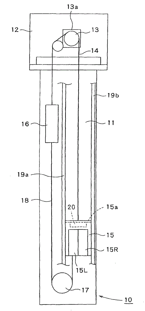
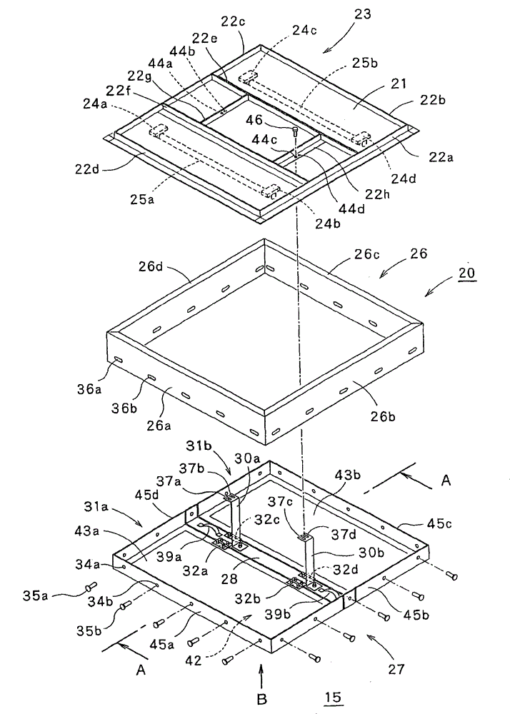
[0029] Below, refer to Figure 1 to Figure 5 , the first embodiment of the present invention will be described.

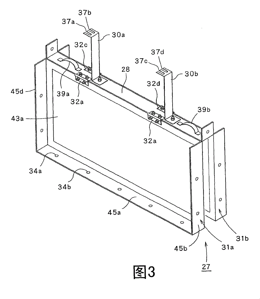
[0030] here, figure 1 It is a schematic diagram showing the overall structure of the elevator system, figure 2 It is an exploded perspective view showing the ceiling lighting device for an elevator according to the present invention. In addition, FIG. 3 is a perspective view showing the ceiling cover in a state (vertical position) in which the rotating part is rotated relative to the fixed part, Figure 4 (a) to (c) are diagrams respectively showing various structures of the design surface of the ceiling cover ( figure 2 B direction to the view), Figure 5 yes figure 2 A cross-sectional view of line A-A.

[0031] First, through figure 1 To illustrate the overall structure of the elevator system.

[0032] Such as figure 1 As shown, the elevator system 10 has an elevator passage 11 arranged in the building, a pair of guide rails 19a, 19b arranged in th...

no. 2 approach

[0058] Next, refer to Image 6 as well as Figure 7 , the second embodiment of the present invention will be described.

[0059] Image 6 It is a perspective view showing the ceiling cover transport trolley and the ceiling cover of the present invention, Figure 7 It is a side view showing a ceiling cover transport trolley and a ceiling cover ( Image 6 C direction of the view). exist Image 6 as well as Figure 7 In the second embodiment shown, for the Figure 1 to Figure 5 The parts that are the same as those in the first embodiment shown are assigned the same reference numerals, and detailed description thereof will be omitted.

[0060] exist Figure 6 to Figure 7 Among them, the ceiling cover transport cart 40 is used to transport the above-mentioned ceiling cover 27 . That is, the ceiling cover 27 has a design surface 42. The design surface 42 has a fixed portion 28 and rotating portions 31a, 31b that are rotatably connected to the fixing portion 28 and provided ...


PUM


Abstract

The present invention provides a plafond illuminating device which can easily change the plafond cover when the refurbishment project of cage plafond is executed. The plafond illuminating device (20) of elevator comprises the following components: a plafond plate (23) which is installed with luminous elements (25a, 25b); and a plafond cover (27) which is configured below the plafond plate and is provided with a space between the plafond cover and the plafond plate. The plafond cover is provided with a design platform (42) comprising transparent parts (43a, 43b). The design surface causes thatthe light from the luminous elements transmits into the cage (15). Additionally, a side cover (26) is configured between the plafond plate and the plafond cover with a mode of surrounding the luminous elements. The plafond cover and the plafond plate can be connected detachably through the supporting posts (30a, 30b) extending in the upper-and-down direction. Therefore the plafond cover can be easily changed when the refurbishment project of cage plafond (15a) is executed.

Description

technical field [0001] The present invention relates to an elevator ceiling lighting device installed on a car ceiling of an elevator and a ceiling cover conveying trolley for carrying the ceiling cover of the ceiling lighting device, and more particularly to an elevator that can easily carry out a renovation project of a car ceiling Canopy lighting and a trolley for transporting the canopy. Background technique [0002] Figure 8 It is a figure which shows the ceiling lighting apparatus of the conventional elevator installed in the car ceiling. exist Figure 8 Among them, a conventional ceiling lighting device 100 has a ceiling plate 101 on which a lamp holder 104 and a fluorescent lamp 105 are mounted, and a cover 102 made of sheet metal is attached to the ceiling plate 101 so as to cover the periphery of the fluorescent lamp 105. The design surface 103 is made of a light-transmitting material such as acrylic. Such a ceiling lighting device 100 is shipped out after be...

Claims


Application Information

Patent Timeline
Patent Type & Authority Patents(China)
IPC IPC(8): B66B11/02F21V33/00B62B3/00
Inventor 渡部正人
Owner TOSHIBA ELEVATOR KK
Learn More