Vane-type compressor

A compressor and vane-type technology, which is applied in the field of compressors, can solve the problems of increasing the number of parts and cost, and achieve the effect of preventing the increase of the number of parts, preventing the increase of cost, and reliable reciprocating movement

Inactive Publication Date: 2009-07-01
CALSONIC KANSEI CORP
View PDF1 Cites 11 Cited by
  • Summary
  • Abstract
  • Description
  • Claims
  • Application Information

AI Technical Summary

Problems solved by technology

Therefore, when the coil spring is extended beyond the length of the guide pin, the coil spring cannot be sufficiently guided by the guide pin, and the coil spring may b

Method used


Image

  • Vane-type compressor
  • Vane-type compressor
  • Vane-type compressor

Examples


Embodiment Construction

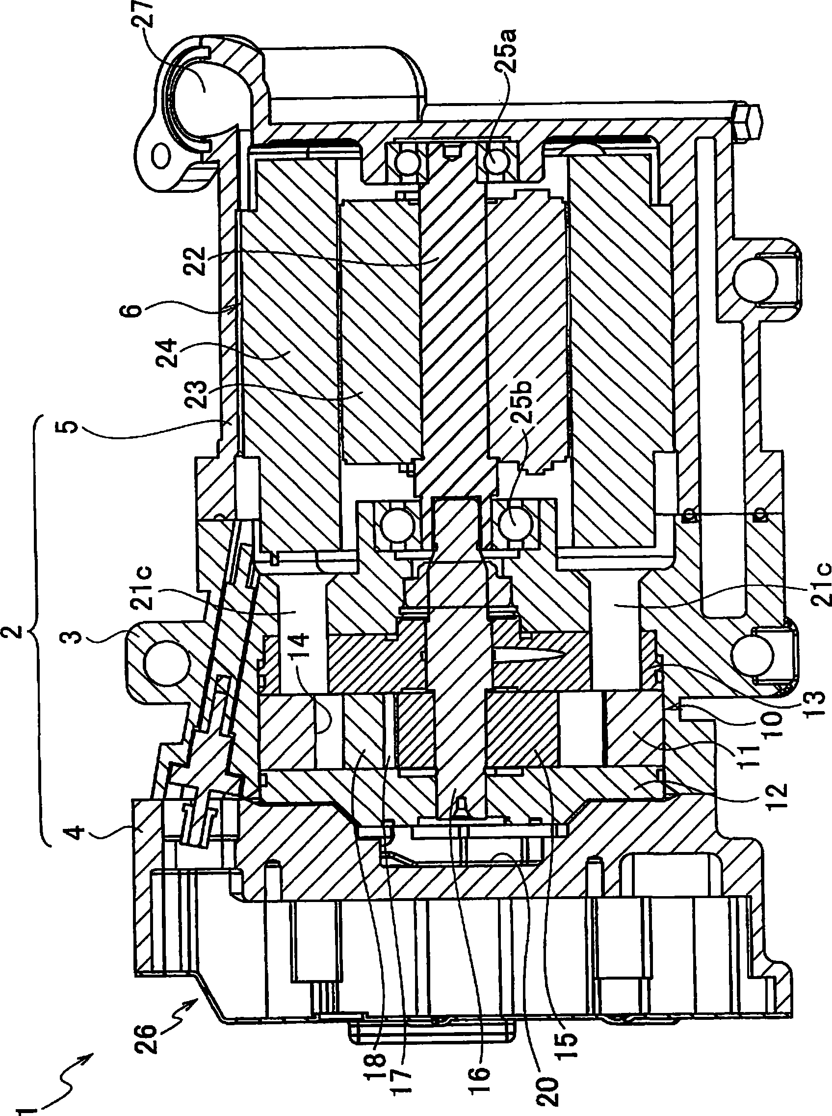
[0054] Hereinafter, embodiments of the present invention will be described with reference to the drawings. First, refer to Figure 1 ~ Figure 3 The first embodiment will be described.

[0055] Such as figure 1 As shown, the compressor 1 has a housing 2 . The housing 2 is composed of a substantially cylindrical compressor housing 3 , a front housing 4 disposed at one open end of the compressor housing 3 , and a motor housing 5 disposed at the other open end of the compressor housing 3 . The compressor casing 3, the front casing 4, and the motor casing 5 are all made of aluminum alloy.

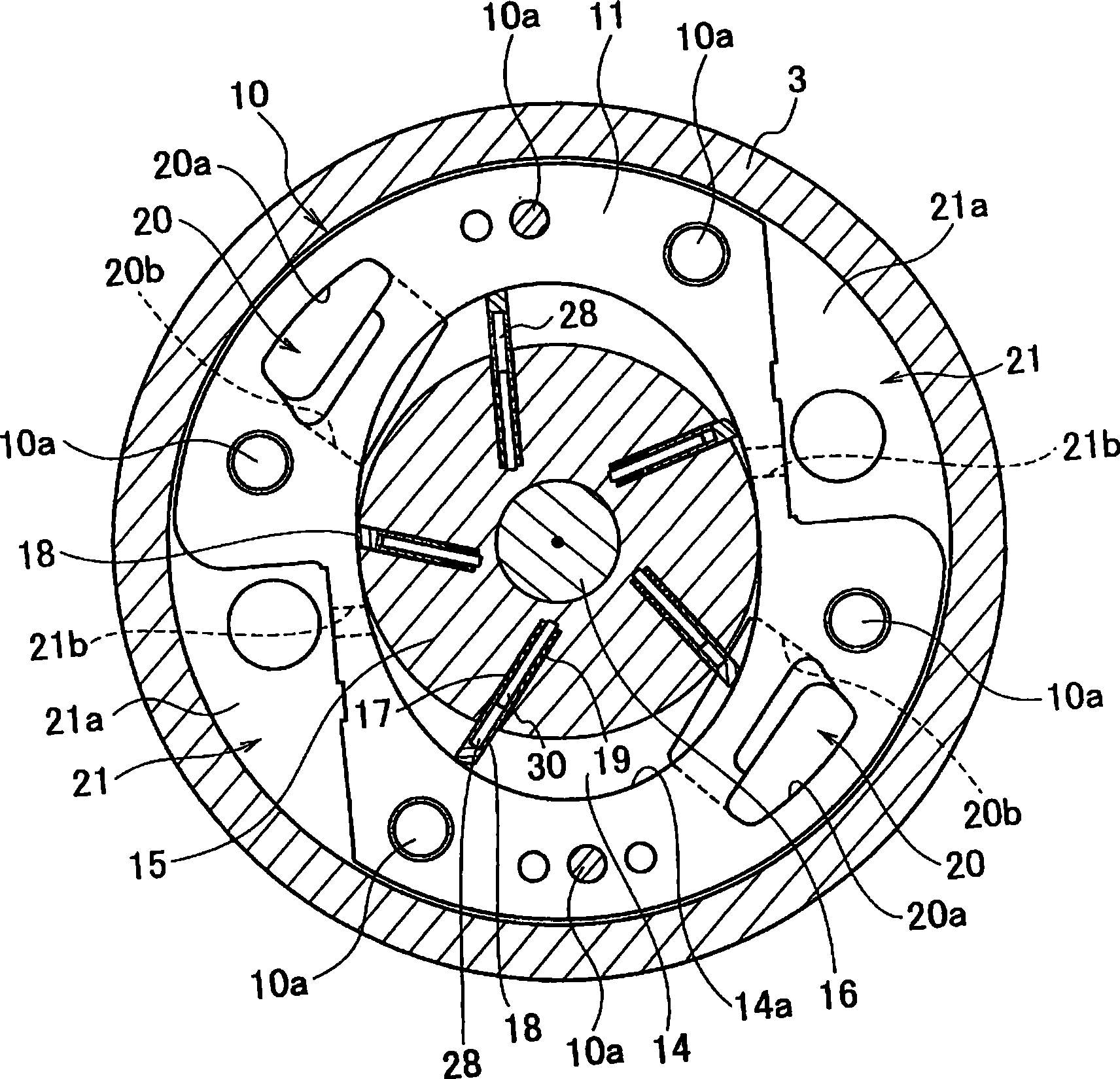
[0056] The compression unit 10 is accommodated in the compressor housing 3 . The compression unit 10 includes a cylinder block 11 , a front cylinder block 12 and a rear cylinder block 13 respectively arranged on two sides of the cylinder block 11 . These cylinder blocks 11, 12, 13 use bolts 10a (refer to figure 2 ) are fastened together. Compression chambers 14 are formed in the cylinder...


PUM


Abstract

A vane-type compressor includes: a cylinder block; a rotor rotating within the cylinder block; vane slots provided on the rotor; vanes each provided slidably within each of the vane slots; coil springs provided within the vane slots for pushing the vanes; guide pins each provided along each of the coil springs and directly fixed on the vanes or the rotor; and guide holes each provided for each of the guide pins and formed on the rotor or the vane. The guide holes are formed on the vanes in case where the guide pins are directly fixed on the rotor. Alternatively, the guide holes are formed on the rotor in case where the guide pins are directly fixed on the vanes. The compressor prevents chattering of the vanes and also prevents a complex structure and cost rise.

Description

technical field [0001] The present invention relates to a compressor for compressing refrigerant by forming a compression chamber in the cylinder body by using a rotor and blades rotating in the cylinder body. Background technique [0002] A "gas compressor" is disclosed in JP 2007-100602 A (Patent Document 1). The gas compressor is a vane compressor. Generally, in vane compressors, oil pressure (back pressure) pressurized by discharge pressure is sent to vane grooves provided in the rotor. Thus, the vanes in the vane grooves are pushed against the inner surface (cam surface) of the compression chamber inside the cylinder block. As a result, the compression function is improved and the vibration between the vane and the cam surface is reduced. Noise caused by vibration is also reduced. [0003] In the gas compressor described above, an auxiliary high-pressure supply path is provided in addition to the normal back pressure supply path. The auxiliary high-pressure supply ...

Claims


Application Information

Patent Timeline
IPC IPC(8): F04C18/344
Inventor 岛口博匡前村好信
Owner CALSONIC KANSEI CORP
Why Eureka
Try Eureka