Condenser

A technology for condensers and condensing parts, applied to evaporators/condensers, refrigerators, refrigeration components, etc., can solve problems such as insufficient design of condensers, and achieve the effect of preventing the increase in the number of components and the reduction in performance

Active Publication Date: 2018-01-19
MAHLE INT GMBH
View PDF11 Cites 0 Cited by
  • Summary
  • Abstract
  • Description
  • Claims
  • Application Information

AI Technical Summary

Problems solved by technology

[0009] However, in the condenser described in Patent Document 2, since the entire refrigerant inflow path of the inlet part exists outside the inlet header

Method used


Image

  • Condenser
  • Condenser
  • Condenser

Examples


Embodiment Construction

[0047] Hereinafter, embodiments of the present invention will be described with reference to the drawings.

[0048] In the following description, the term "aluminum" includes not only pure aluminum but also aluminum alloys.

[0049] Moreover, the same code|symbol is attached|subjected to the same part and the same component in all drawings.

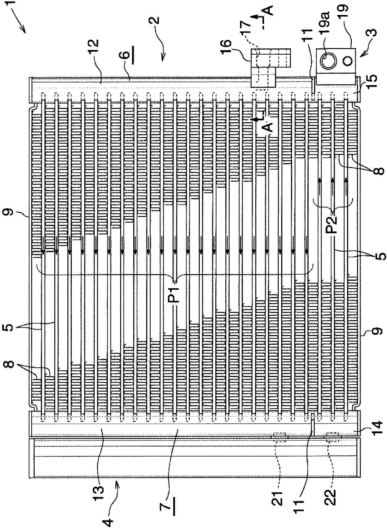
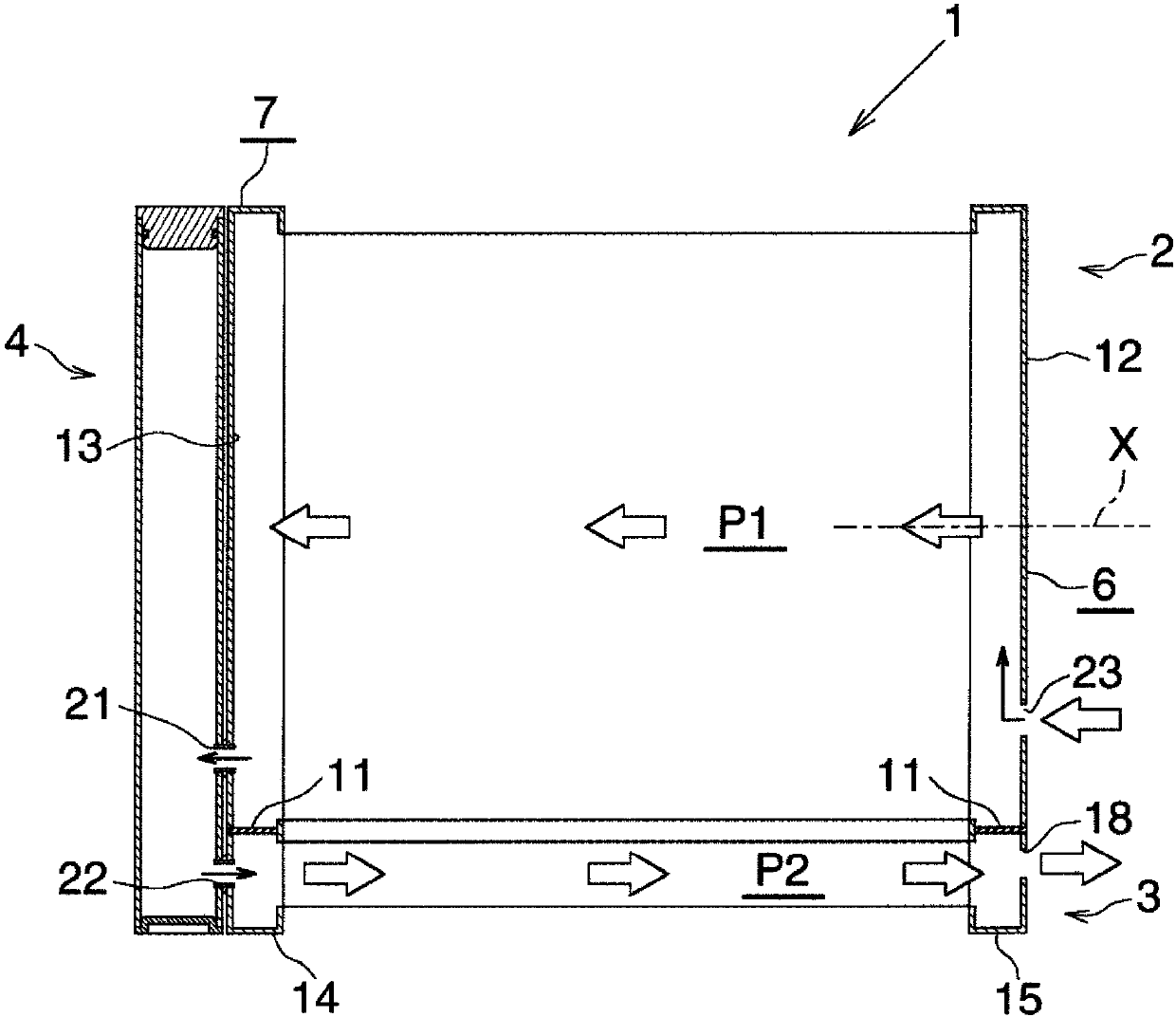
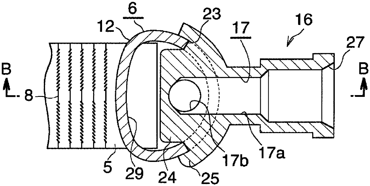
[0050] figure 1 Concretely showing the overall configuration of the first embodiment of the condenser of the present invention, figure 2 Schematically express figure 1 the condenser, Figure 3 ~ Figure 5 express figure 1 The composition of the main part of the condenser. exist figure 2 In , illustration of each heat exchange tube is omitted, and illustration of corrugated fins and side plates is also omitted.

[0051] exist figure 1 as well as figure 2 Among them, the condenser 1 is composed of a condensing part 2, a supercooling part 3 arranged under the condensing part 2, and an aluminum box-shaped liquid receiver 4 (liquid ...


PUM


Abstract

The invention provides a condenser which enables a flux of refrigerant liquid flowing inside a heat exchange path for condensing by a refrigerant to be homogenized and can realizes miniaturized. An inlet member is connected to a liquid collection case arranged at an inlet of a condensing part of the condenser. The inlet member (16) has a refrigerating fluid influx path (17) having two opened ports. One end of the refrigerant influx path of the inlet member is opened to become an inlet (27) for the fluid flowing from the outside. The other opened end is an outlet port through which a fluid canflow to the liquid collection case at the inlet of the condensing part. An opening is formed on the circumferential wall of liquid collection case at the inlet of the condenser and is deviated to oneend side relative to the central part along a length direction. An inserting part (24) which goes through the opening and is inserted into the the condensing part is arranged on the inlet member (16).The flow-out port for the refrigerant liquid is open facing to a plane facing upwards in the inserting part to make the refrigerant liquid the flow to the outside along the central part side of the length direction of the liquid collection case arranged at the inlet of the condenser.

Description

technical field [0001] The present invention relates to a condenser suitable for use in, for example, an automobile air conditioner mounted on an automobile. [0002] In this specification and claims, up and down, left and right are figure 1 , Figure 11 , Figure 15 as well as Figure 17 Up and down, left and right, with figure 1 , Figure 11 , Figure 15 as well as Figure 17 The direction of the front and back of the paper is the ventilation direction. Background technique [0003] For example, as a condenser of an automobile air conditioner, a condenser is widely known, which has a condensing part, and the condensing part has: at least one heat exchange path composed of a plurality of heat exchange tubes, wherein the plurality of heat exchange tubes The longitudinal direction faces the left and right directions and is arranged side by side at intervals along the up and down direction; the condensing part inlet liquid collection tank is arranged with the longitudi...

Claims


Application Information

Patent Timeline
IPC IPC(8): F25B39/04F28F9/02F28F1/22
Inventor 有野康太
Owner MAHLE INT GMBH
Why Eureka
Try Eureka