Plate-type non-return valve

A one-way valve and plate-type technology, which is applied in the field of hydraulic control valves, can solve problems such as the failure to meet the opening pressure requirements, the opening position of the poppet valve is not large enough, and the service life of the spring is shortened, so as to increase the fit clearance, prevent oil trapping, and use The effect of increasing lifespan

Inactive Publication Date: 2009-07-01
SHANGHAI LIXIN HYDRAULIC
View PDF0 Cites 2 Cited by
  • Summary
  • Abstract
  • Description
  • Claims
  • Application Information

AI Technical Summary

Problems solved by technology

In the traditional structure, the distance between the oil sealing port of the cone valve and the oil outlet P2 is small, which makes the opening position of the cone valve not large enough. The service life of the spring is shortened due to the close pressure and size. Due to the position limitation, only one spring opening pressure can be designed, which cannot meet various opening pressure requirements. The spring seat and the end cover adopt a split structure, and the spring seat needs to be installed The oil groove prevents oil trapping. The gap between the spring seat and the cone valve is small, which makes the processing and assembly cumbersome. The limit of the cone valve is limited by the left end surface of the spring seat, so that the impact and collision during work are concentrated on The shoulder of the cone valve affects the service life of the cone valve

Method used


Image

  • Plate-type non-return valve
  • Plate-type non-return valve
  • Plate-type non-return valve

Examples


Embodiment

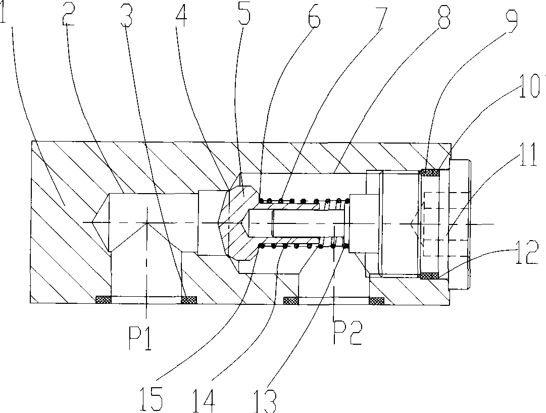
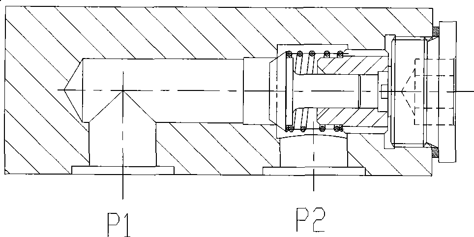
[0023] Such as figure 1 shown for explanation. When the hydraulic oil flows in from the P1 port and flows out from the P2 port. The plate check valve shown in the figure is in the closed state. As the oil flow increases, the oil overcomes the opening pressure of the spring 7 to move the cone valve 5 to the right on the left end guide surface of the end cover 11. At this time, the two chambers of P1 and P2 communicate. , the oil flows out from the P2 port. When the left end face of the end cover 11 is in contact with the inner hole wall of the poppet valve 5, the poppet valve 5 stops moving. 5 moves to the left and closes until the oil sealing surface 4 of the cone valve 5 contacts the oil sealing port of the valve body 1 to realize positive fluidity.

[0024] When the pressure oil enters from the P2 cavity, the pressure oil enters the spring cavity and acts on the shoulder and head of the cone valve 5, the cone valve 5 remains on the oil sealing surface 4, and no oil flows...


PUM


Abstract

A plate check valve, relating to the field of hydraulic control valve, comprises a valve body, wherein a main hole, opened in the center of the valve body, is in the form of step blind hole, screws are arranged on the shoulder surface on the right end of the valve body; a bottom plate arranged on the bottom part of the valve body, wherein an oil inlet P1 and an oil outlet P2 are opened on the bottom surface of the valve body and communicated with the main hole of the valve body, and a sealing ring is arranged at the interface of the oil inlet P1 and the oil outlet P2 and the bottom surface of the valve body; a cone valve arranged in the main hole, wherein the end part of the cone valve is arranged to be cone-shaped, the cone body is arranged to be a cylinder, the step part of the end part and the cone body is arranged to be chamfer; an end cover arranged on the right end of the valve body, wherein the outside of the end cover is provided with screws which are fit with the screws on the shoulder surface on the right end of the valve body, the interface of the end cover and the valve body is sealed through the sealing ring and a retaining ring; a spring arranged on the cylindrical surface on the right end of the cone valve, wherein one end of the spring is contacted with the step part of the end and the valve body, the other end is sleeved on the shoulder surface of the end cover.

Description

Technical field: [0001] The invention relates to the field of hydraulic control valves, in particular to a plate-type one-way valve for controlling one-way flow of an oil circuit. Background technique: [0002] At present, the plate check valve is a check valve connected by a bottom plate, which only allows the oil to flow in one direction and cut off in the reverse direction. For the structure of the traditional plate check valve, please refer to the attached figure 2 and attached image 3 . In the traditional structure, the distance between the oil sealing port of the cone valve and the oil outlet P2 is small, which makes the opening position of the cone valve not large enough. The service life of the spring is shortened due to the close pressure and size. Due to the position limitation, only one spring opening pressure can be designed, which cannot meet various opening pressure requirements. The spring seat and the end cover adopt a split structure, and the spring seat...

Claims


Application Information

Patent Timeline
IPC IPC(8): F16K15/12F15B13/02
Inventor 袁才富朱剑根张妮沈至伟
Owner SHANGHAI LIXIN HYDRAULIC
Why Eureka
Try Eureka