Eureka AIR delivers breakthrough ideas for toughest innovation challenges, trusted by R&D personnel around the world.

Construction engineering repair working frame

A technology for maintenance work and construction engineering, applied in construction, building structure, accessories of scaffolding, etc., can solve problems such as affecting work, danger, inconvenience, etc. Effect

Inactive Publication Date: 2017-08-18
张志通
View PDF6 Cites 2 Cited by
  • Summary
  • Abstract
  • Description
  • Claims
  • Application Information

AI Technical Summary

Problems solved by technology

[0002] At present, in the field of construction engineering, more and more attention is paid to building maintenance. The maintenance work of some small and low buildings has attracted people's attention. The traditional building maintenance equipment is very lacking, and often uses tools such as lap springboards and tables and chairs for construction. Work maintenance is often not very convenient in the process of building construction, and it is very dangerous. For example, applying for existing work frames, including column A, column B, column C, column D, column A and column B, column C It is connected with column D through connecting rods and workbench fixing rods. Column A is connected with column D, column B and column C through a set of intersecting inclined beams. The inclined beams are connected with column A, column B, Column C, column connection, column A, column B, column C, and column D have universal wheels at the lower end, although the stability of the bottom end has been improved to a certain extent, but a variety of tools are usually used inside during work, so tools need to be placed The tool box is used to store tools, and a short ladder needs to be installed to assist maintenance work, which leads to a large internal space occupation and affects the work.

Method used


Image

  • Construction engineering repair working frame
  • Construction engineering repair working frame
  • Construction engineering repair working frame

Examples


Embodiment 1

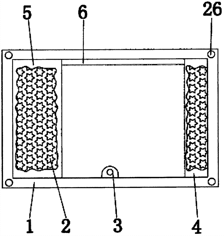
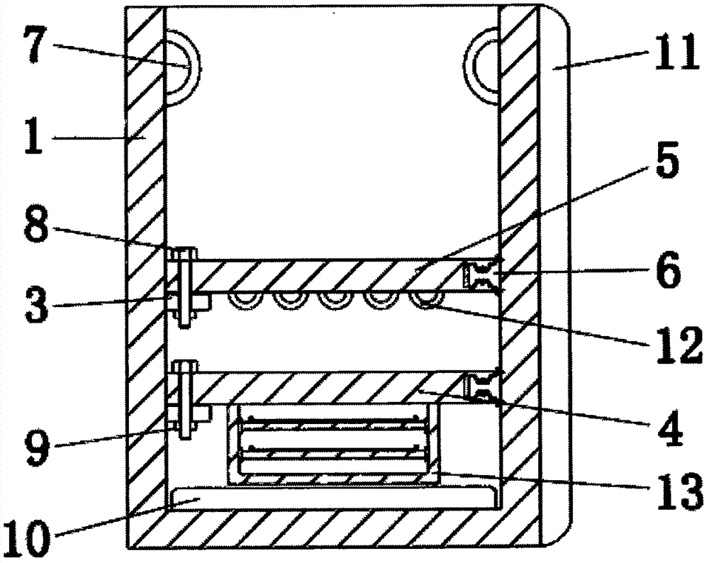
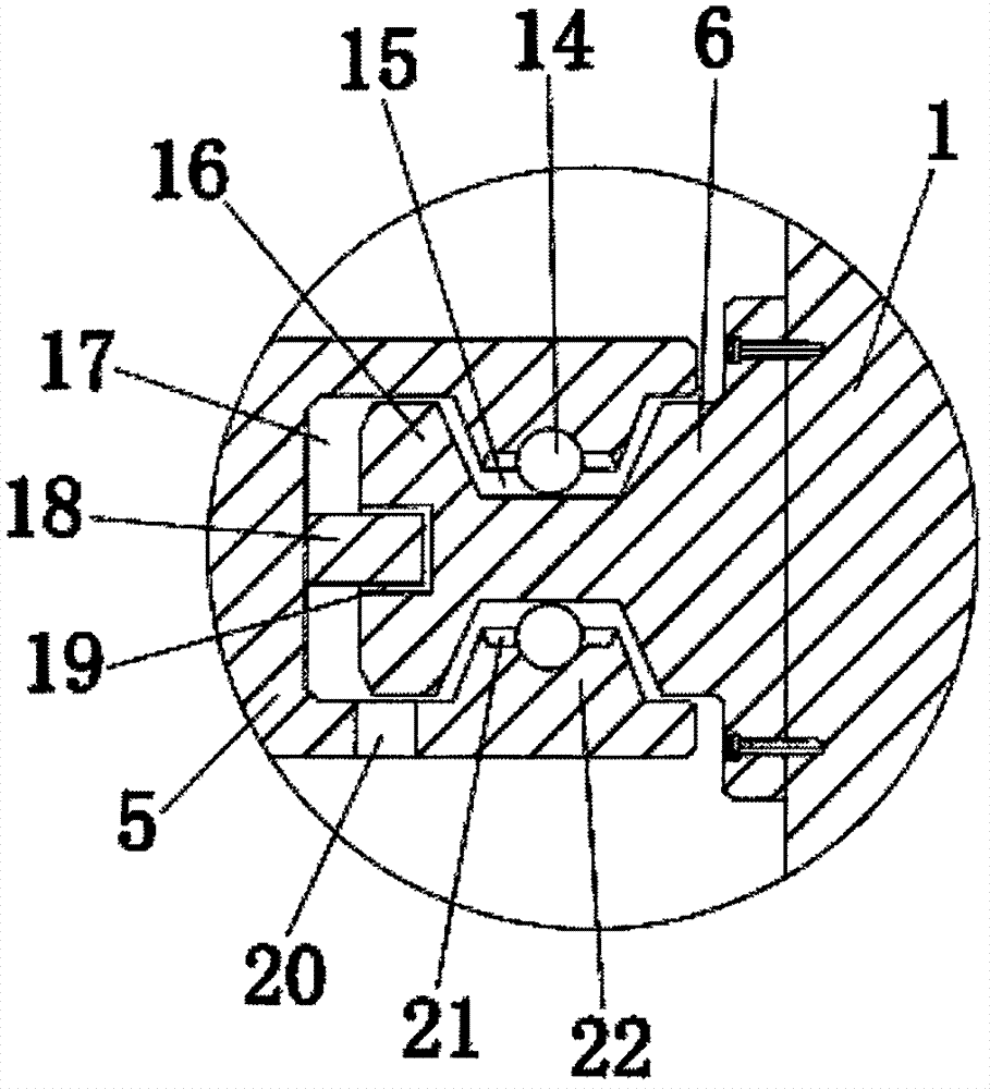
[0021] Example 1: Please refer to Figure 1-6 , the present invention provides a technical solution: a construction maintenance work stand, including a frame body 1, a foam backing plate 11 is pasted on the right side of the outer wall of the frame body 1, and handles are installed on the left and right sides of the inner top of the frame body 1 7. The four corners of the front of the frame body 1 are provided with a central tube 26, and the outer top of the central tube 26 is sleeved with a pressure seat 25, and the pressure seat 25 is connected with the frame body 1 and the central tube 26 through fixing bolts 24, and the center tube 26 The bottom rod 29 is connected through the inside, and the top of the bottom rod 29 is equipped with a suspension ring 28. A tightening tube 30 is installed at the top of the connection between the central tube 26 and the bottom rod 29, and a gland 27 is installed on the top of the tightening tube 30 to tighten The cylinder 30 is a rubber cyl...


PUM


Abstract

The invention discloses a maintenance work frame for construction engineering, which comprises a frame body, a second platform and a first platform are respectively arranged on the left and right sides inside the frame body, and a track is installed on the inner rear side of the frame body, An overlapping platform is installed at the center of the inner front side of the frame body, and a tool rack is installed at the bottom end of the first platform. The maintenance work frame for construction engineering pushes and pulls the first table and the second table to make the right side move on the track through the cooperation of the first table, the second table and the tool rack. At this time, the workers can stand on the first table respectively One plate and the second plate are used to increase the working height, which can be used as a short ladder, and can be moved to one end of the work frame when not in use. The tools used can be hooked on the hanging ring, which is convenient for storing and taking out tools , The stored tools are arranged inside the first table and the second table, and the use space inside the work frame is reasonably planned, which facilitates the work.

Description

technical field [0001] The invention relates to the technical field of construction machinery, in particular to a maintenance work frame for construction engineering. Background technique [0002] At present, in the field of construction engineering, more and more attention is paid to building maintenance. The maintenance work of some small and low buildings has attracted people's attention. The traditional building maintenance equipment is very lacking, and often uses tools such as lap springboards and tables and chairs for construction. Work maintenance is often not very convenient in the process of building construction, and it is very dangerous. For example, applying for existing work frames, including column A, column B, column C, column D, column A and column B, column C It is connected with column D through connecting rods and workbench fixing rods. Column A is connected with column D, column B and column C through a set of intersecting inclined beams. The inclined be...

Claims


Application Information

Patent Timeline
Patent Type & Authority Applications(China)
IPC IPC(8): E04G1/15E04G5/00
CPCE04G1/15E04G5/003E04G2001/157
Inventor 张志通朱翔徐淑辉
Owner 张志通
Why Eureka
Eureka Blog
Learn More