Depth measurement for sound impulse emitter by utilization of seismic spread

A technology for transmitters and bathymetry, applied in measuring devices, geophysical surveys, instruments, etc., can solve time-consuming and expensive problems

Inactive Publication Date: 2009-07-01
GECO TECH BV
View PDF1 Cites 2 Cited by
  • Summary
  • Abstract
  • Description
  • Claims
  • Application Information

AI Technical Summary

Problems solved by technology

This method of obtaining bathymetric charts of an area is expensive and time consuming

Method used


Image

  • Depth measurement for sound impulse emitter by utilization of seismic spread
  • Depth measurement for sound impulse emitter by utilization of seismic spread
  • Depth measurement for sound impulse emitter by utilization of seismic spread

Examples


Embodiment Construction

[0012] Reference is now made to the drawings in which: elements shown are not necessarily to scale and like or like elements are indicated by like numerals throughout the several views.

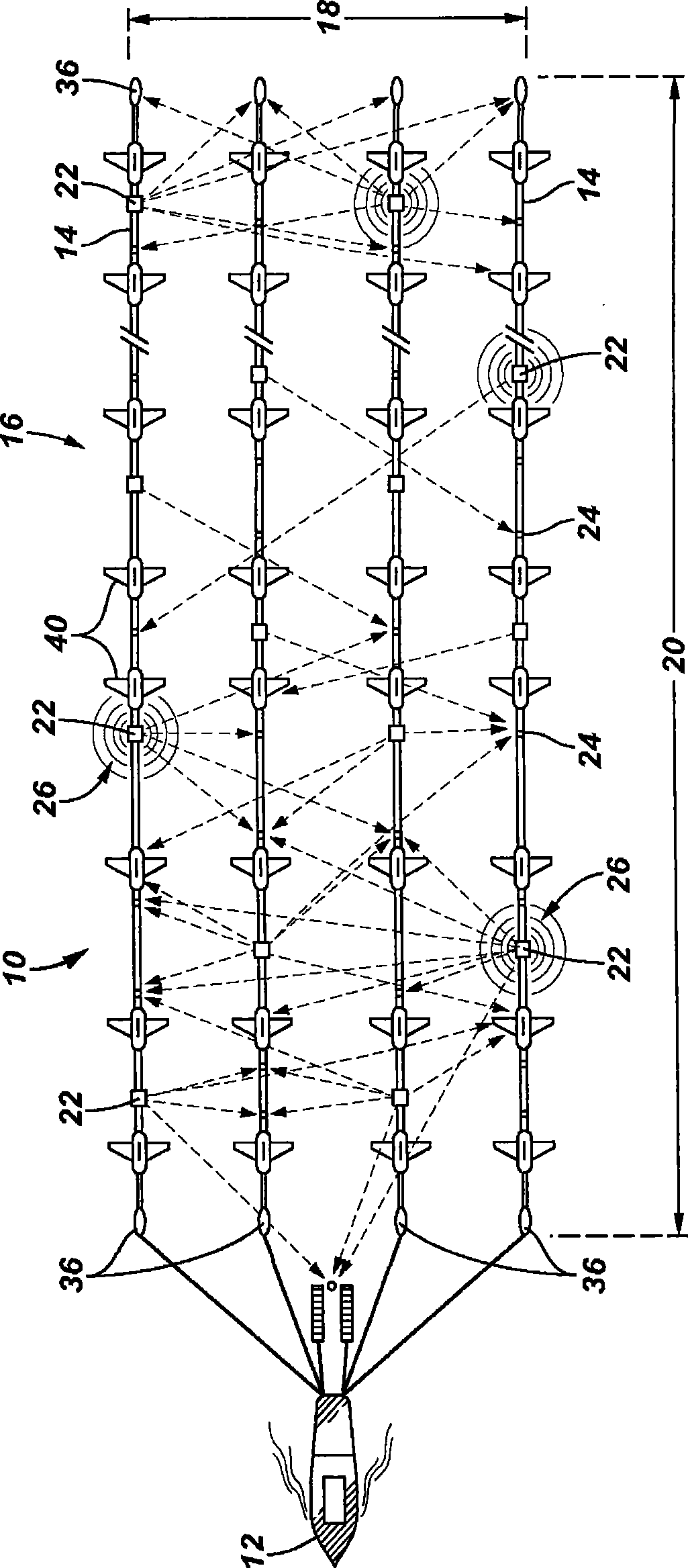
[0013] figure 1 is a top view of an embodiment of the depth measurement system of the present invention, generally indicated at 10 . System 10 may be an acoustic ranging system such as that described in US Patent No. 5,668,775. System 10 includes vessel 12 towing one or more marine seismic streamers 14 . Marine seismic streamers 14 extend longitudinally from vessel 12 and are spaced laterally from one another to form a seismic array 16 for taking seismic measurements. It is not uncommon for seismic arrays 16 to extend 300 to 1200 meters laterally (indicated by 18), and 3 to 12 kilometers longitudinally (indicated by 20).

[0014] The seismic array 16 includes an acoustic ranging system for navigation and positioning purposes. The acoustic ranging system includes a plurality of transmitter...


PUM


Abstract

The invention discloses a method for measuring water depth across the seismic array, comprising: emitting signals via an acoustic pulse emitter in seismic array; measuring the arrival time of the signal bottom reflected to a receiver in a seismic geophone; measuring the time of the signal directly reaching the receiver; and determining water depth according to the measured arrival time of the signals.

Description

technical field [0001] The present invention relates generally to marine seismic surveys, and more particularly to systems and methods for producing bathymetry across a seismic spread by using components of a seismic spread. Background technique [0002] In marine seismic surveying, it is desirable to have accurate information about the water depth across the seismic array. This depth information is important to avoid adding bottom reflections in positioning solutions and to remove waterborne multiples in seismic data processing. To date, water depths have generally been taken along seismic survey tracks using echo sounders mounted on the hull of a vessel. The depth information obtained in this way is of little value because it only characterizes a limited area and does not cover the seismic array. Multiple round trips with a survey vessel using multiple echosounders or side-scan sonars can obtain more precise depth information for chart generation. This method of obtaini...

Claims


Application Information

Patent Timeline
Patent Type & Authority Applications(China)
IPC IPC(8): G01B21/18G01C13/00G01V1/00
Inventor 斯韦恩·阿尔内·弗里维克伦德特·孔贝伊
Owner GECO TECH BV
Why Eureka
Try Eureka