An exposure head and an image forming apparatus

An exposure head and image technology, applied in the field of exposure heads, can solve problems such as poor exposure

Inactive Publication Date: 2009-07-01
SEIKO EPSON CORP
View PDF1 Cites 1 Cited by
  • Summary
  • Abstract
  • Description
  • Claims
  • Application Information

AI Technical Summary

Problems solved by technology

Therefore, in some cases, various exposure defects may occur due to t...

Method used


Image

  • An exposure head and an image forming apparatus
  • An exposure head and an image forming apparatus
  • An exposure head and an image forming apparatus

Examples


Embodiment Construction

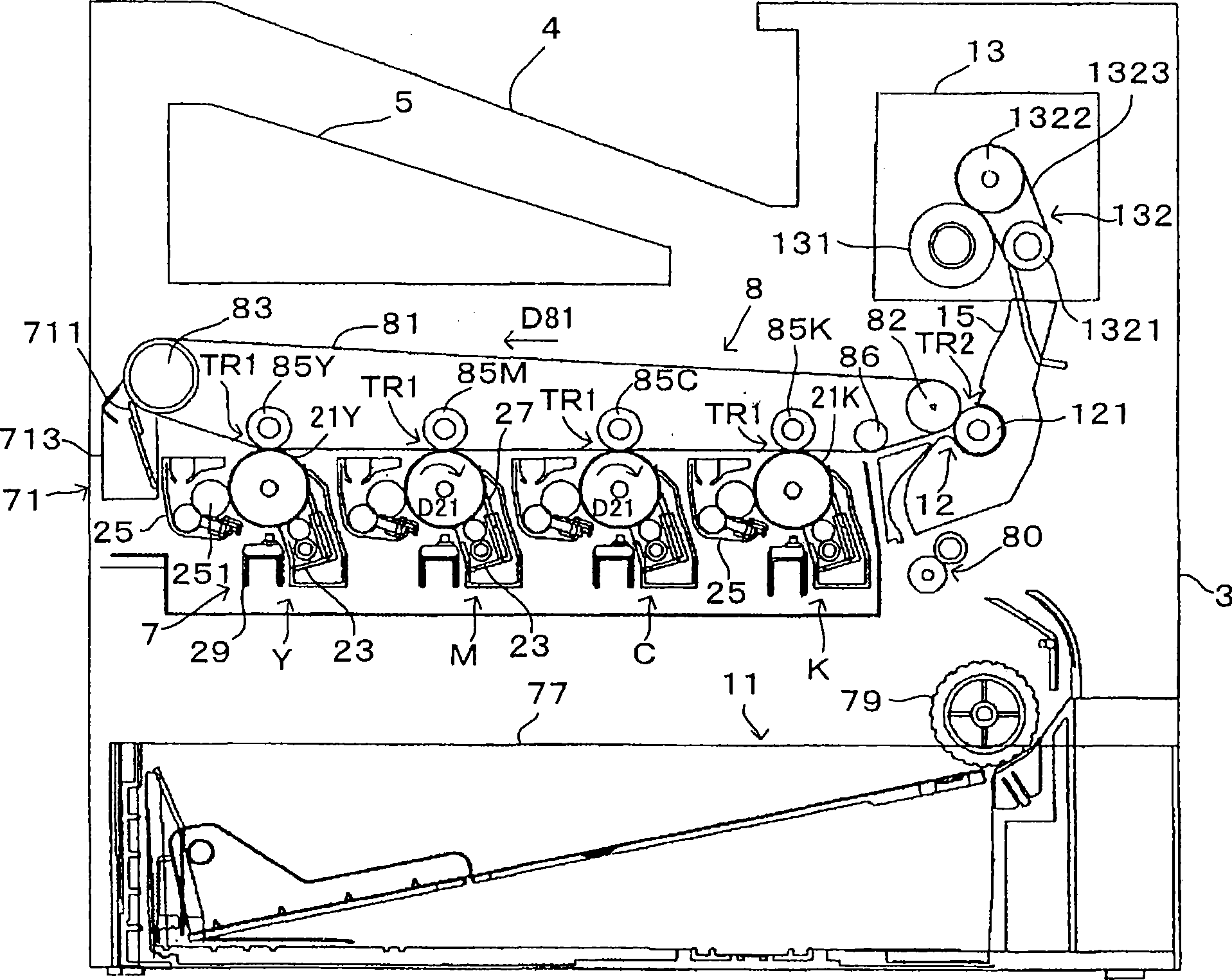
[0069] Hereinafter, terms used in this specification will first be described (refer to the item "A. Explanation of terms"). Following the description of the terms, the basic structure of the image forming apparatus equipped with the line head to which the present invention is applied (refer to the item of "B. Basic structure"), and the basic operation of the line head (refer to "C. .basic work" item) for description. Next, following the description of these basic structures and basic operations, an embodiment of the present invention will be described.

[0070] A. Explanation of terms

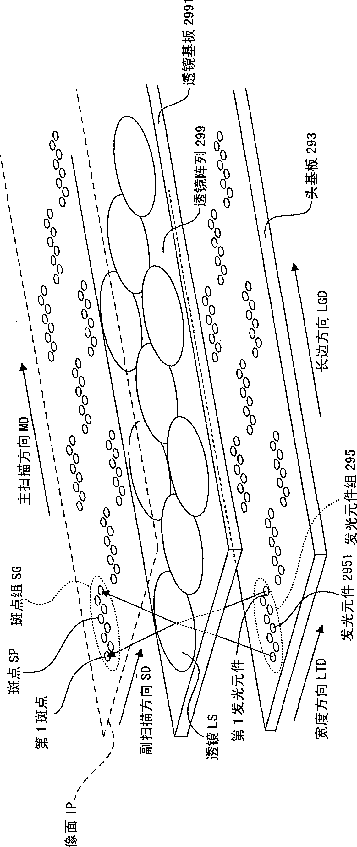
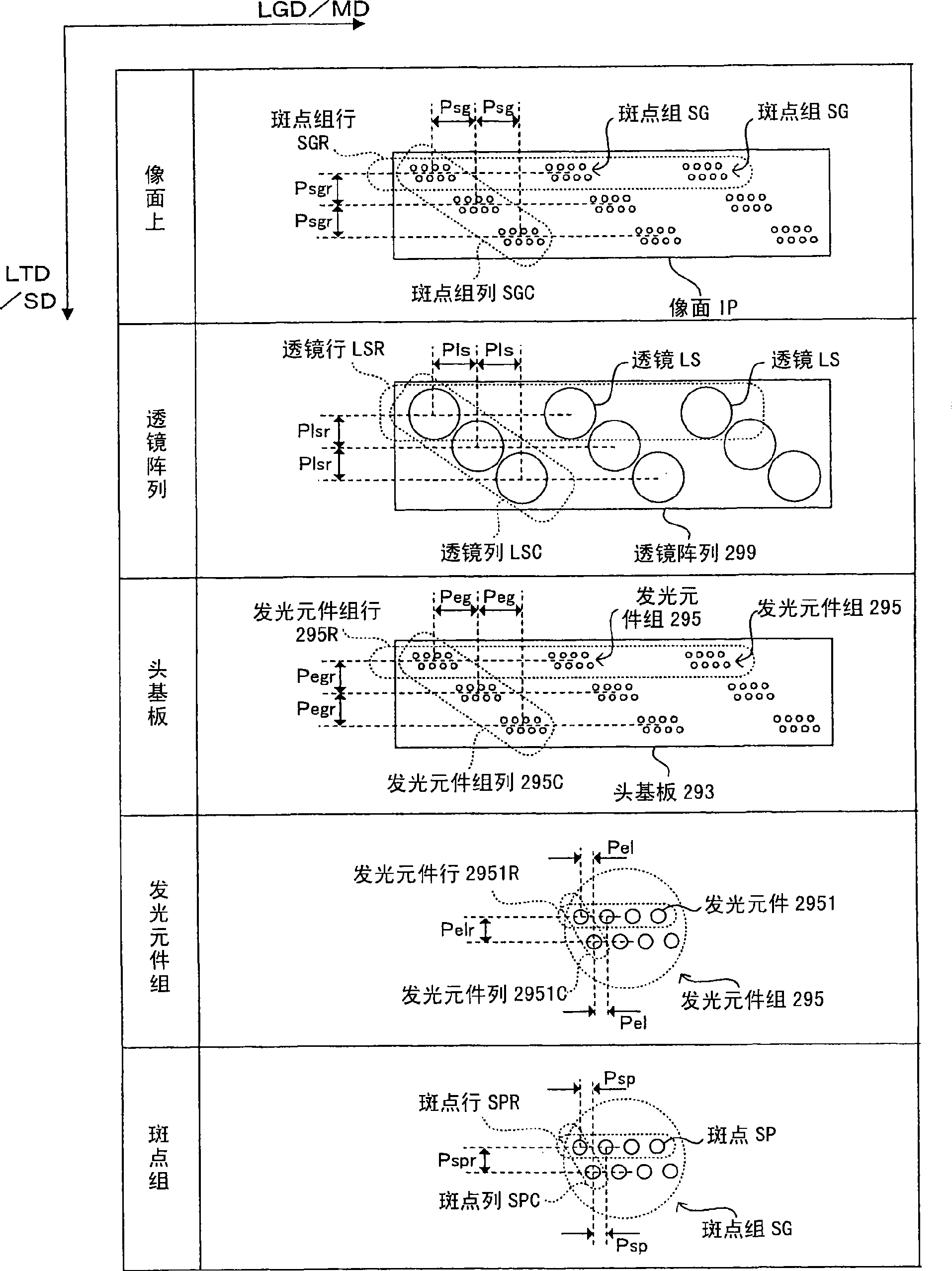
[0071] figure 1 with figure 2 It is an explanatory diagram of terms used in this specification. Here, terms used in this specification will be organized using these drawings. In this specification, the conveying direction of the surface (image plane IP) of the photoreceptor drum 21 is defined as a sub-scanning direction SD, and a direction perpendicular or substantially perpendicular to t...


PUM


Abstract

The invention provides the technology for inhibiting bad exposure caused by different speckle formation positions in the first direction. An image formation device of the invention comprises a latent image supporting body moving in the first direction (SD), an exposure head (29) with a first imaging optical system (LS_1), a second imaging optical system (LS_2) arranged on the first direction side of the first imaging optical system (LS_1), a luminous element gives light to the first imaging optical system to image on the latent image supporting body and gives light to the second imaging optical system to image the latent image supporting body, and a control part for controlling the quantity of light given by the luminous element for the first imaging optical system (LS_1) to image on the latent image supporting body according to the imaging property of the first imaging optical system (LS_1).

Description

technical field [0001] The present invention relates to an exposure head that emits light from a light-emitting element to form a spot, and an image forming apparatus using the exposure head. Background technique [0002] Conventionally, there is known a technique of exposing an image surface such that a line head (exposure head) forms spots on an image surface moving in a sub-scanning direction. In addition, as such a line head, for example, a line head described in Patent Document 1, in which a plurality of light emitting elements are arranged in a line in a main scanning direction perpendicular or substantially perpendicular to a sub scanning direction, can be used. That is, in an exposure operation using such a line head, a plurality of light emitting elements of the line head emit light to form a plurality of spots arranged in the main scanning direction on the image plane. And, such a spot forming operation is repeatedly performed so that the entire image plane is exp...

Claims


Application Information

Patent Timeline
IPC IPC(8): G03G15/01B41J2/447G03G15/00
Inventor 辻野净士井上望野村雄二郎井熊健
Owner SEIKO EPSON CORP
Why Eureka
Try Eureka