beauty device
A technology for generating a device and a rotor, which is applied to devices for washing hair or scalp, hairdressing equipment, mixers with rotary stirring devices, etc., can solve problems such as inability to obtain cosmetic effects, and achieve the effect of suppressing size deviations
- Summary
- Abstract
- Description
- Claims
- Application Information
AI Technical Summary
Problems solved by technology
Method used
Image
Examples
no. 1 Embodiment approach
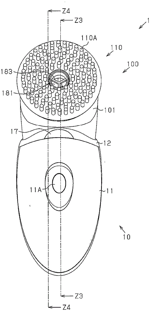
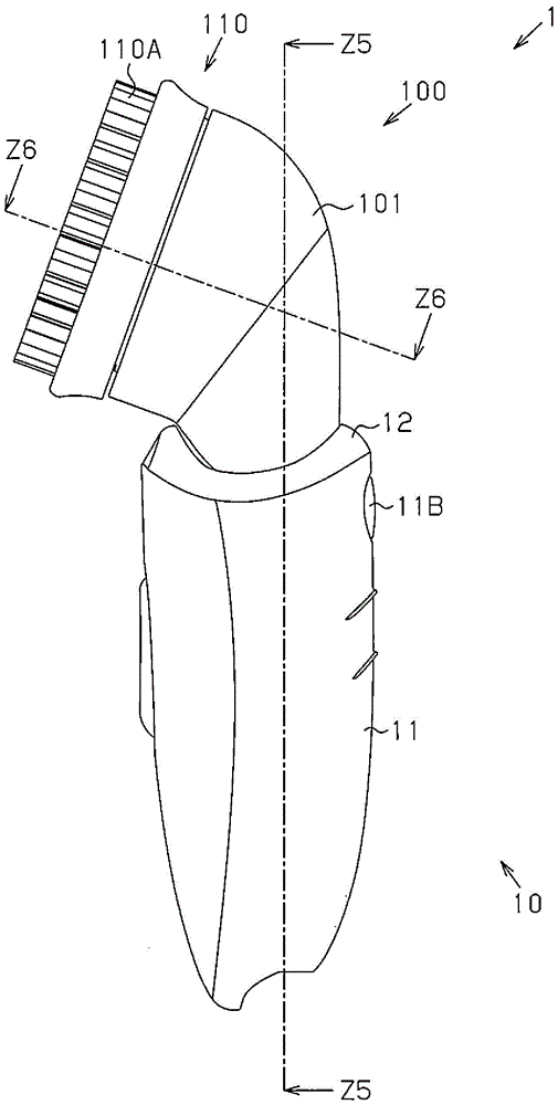
[0062] refer to figure 1 and figure 2 , the appearance structure of the cosmetic device 1 will be described.
[0063] The cosmetic device 1 has a structure suitable for suppressing variation in the size of air bubbles and generating a large amount of fine foam. The foam generated by the cosmetic device 1 can impart a cosmetic effect to the skin. The cosmetic device 1 includes a plurality of functionally combineable components. The cosmetic device 1 includes a main body assembly 10, a head assembly 100, and a head cover 20 (refer to Figure 9 ). The head assembly 100 has a fitting structure that can be attached to and detached from the body assembly 10 . The head assembly 100 has a curved shape as it goes from the body assembly 10 toward the top end of the head assembly 100 .
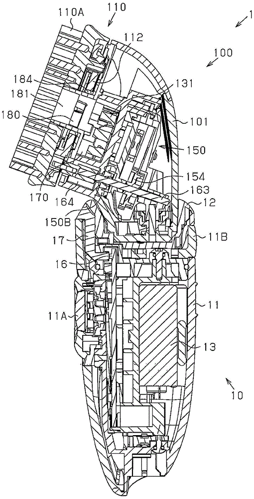
[0064] refer to Figure 3 to Figure 5 , the internal structure of the beauty device 1 will be described. like image 3 As shown, the main body assembly 10 includes a housing 11, a cover 12, a m...
no. 2 Embodiment approach
[0129] refer to Figure 11 and Figure 12 , the external appearance structure of the cosmetic device 2 according to the second embodiment will be described. In the cosmetic device 1 of the first embodiment, the head unit 100 including one brush 110A is provided. On the other hand, in the cosmetic device 2 of the second embodiment, a head unit 200 including three brushes is provided instead of the head unit 100 .
[0130] refer to Figure 13 to Figure 15 , the internal structure of the head assembly 200 is described. For example, the head assembly 200 includes a head housing 201, a brush unit 210, and a foam generating device 220 (refer to 16A to 16C ).
[0131] The brush unit 210 is an example of a beauty unit. The brush unit 210 functions to bring cosmetic effects to the skin by applying gentle physical stimulation to the skin. In this example, the brush unit 210 includes a first brush 210A, a second brush 210B, a third brush 210C, an elastic member group 270, three c...
no. 3 Embodiment approach
[0157] refer to Figure 17 and Figure 18 , the external appearance structure of the cosmetic device 3 according to the third embodiment will be described. In the cosmetic device 1 according to the first embodiment described above, the head unit 100 including one brush 110A is provided. On the other hand, in the cosmetic device 3 of the third embodiment, a head unit 300 including a depilation mechanism is provided instead of the head unit 100 .
[0158] refer to Figure 19 , the internal structure of the head assembly 300 is described. For example, the head assembly 300 includes a head housing 301, a depilation unit 310, and a foam generating device 320 (refer to Figure 20 ).
[0159] The hair removal unit 310 is an example of a beauty unit. The hair removal unit 310 plays a role of bringing cosmetic effects to the skin by pulling out body hair from the skin. The epilation unit 310 has a drum shape. The opening and closing claws 311 are formed on the outer circumferen...
PUM
 Abstract
Description
Claims
Application Information
 - R&D
- Intellectual Property
- Life Sciences
- Materials
- Tech Scout
- Unparalleled Data Quality
- Higher Quality Content
- 60% Fewer Hallucinations
Browse by: Latest US Patents, China's latest patents, Technical Efficacy Thesaurus, Application Domain, Technology Topic, Popular Technical Reports.
© 2025 PatSnap. All rights reserved.Legal|Privacy policy|Modern Slavery Act Transparency Statement|Sitemap|About US| Contact US: help@patsnap.com


