Method for producing r-t-b sintered magnet

A technology of sintered magnets and manufacturing methods, which is applied in the manufacture of inductors/transformers/magnets, magnetic objects, magnetic materials, etc., can solve the problems of difficulty in high-precision grinding, long processing time, large processing load, etc. Deviation and the effect of improving utilization efficiency

Pending Publication Date: 2021-09-28
HITACHI METALS LTD
View PDF1 Cites 0 Cited by
  • Summary
  • Abstract
  • Description
  • Claims
  • Application Information

AI Technical Summary

Problems solved by technology

[0006] However, the sintered body of rare earth alloy magnets such as R-Fe-B magnets is very hard and brittle, and the processing load is large, so high-precision grinding is difficult and takes a long time.
Therefore, processing steps have become a major cause of increased manufacturing costs

Method used


Image

  • Method for producing r-t-b sintered magnet
  • Method for producing r-t-b sintered magnet
  • Method for producing r-t-b sintered magnet

Examples


Embodiment Construction

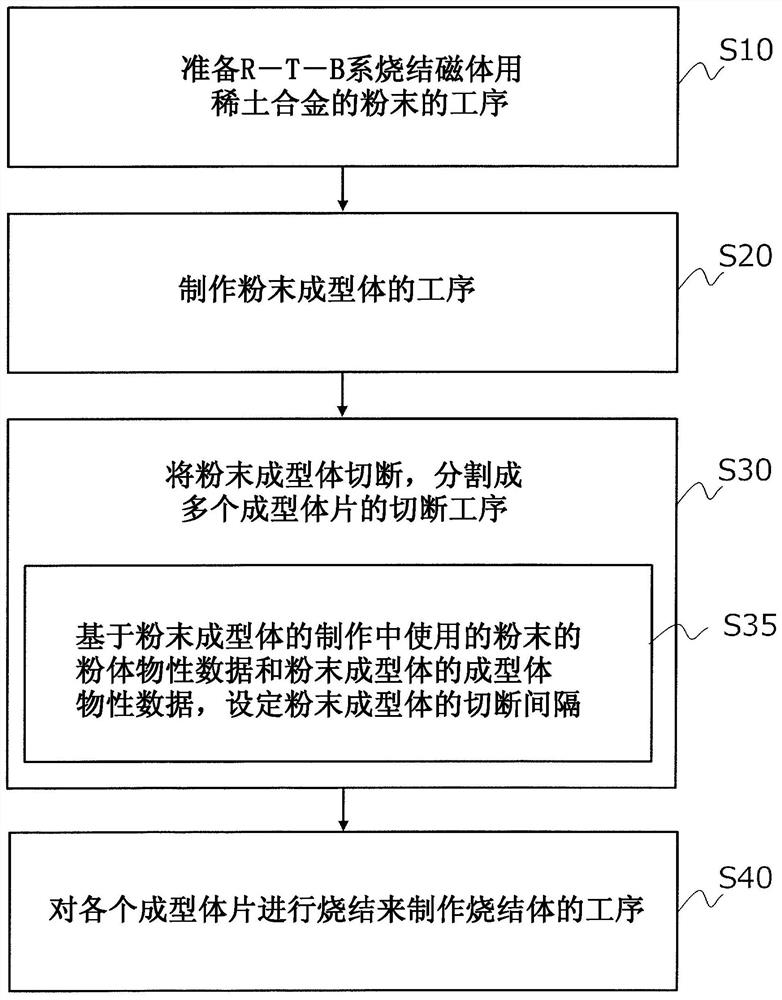
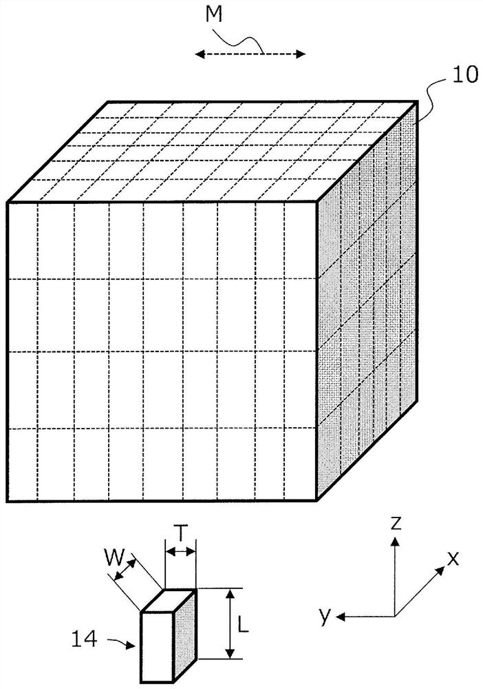
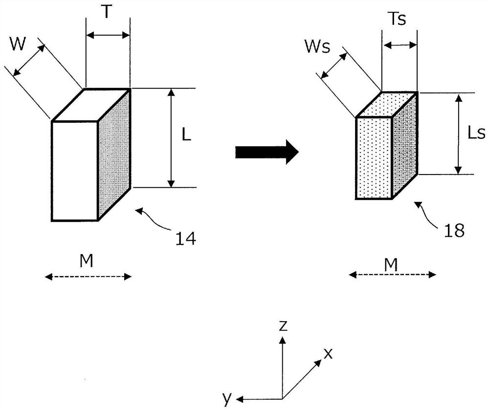
[0027] When a powder compact is cut to prepare a plurality of compact pieces, and each compact piece is sintered to produce a sintered body, shrinkage as described above occurs. The dimensional difference between the molded body and the sintered body with respect to the size of the molded body is defined as "shrinkage rate". The shrinkage rate is, for example, about 30%, but its specific value can vary depending on parameters such as powder composition, particle size, and molding density of the powder compact. The size of the obtained sintered body may vary by, for example, about 2 to 5% due to fluctuations in shrinkage.

[0028] When cutting a powder compact with a wire saw or the like and dividing it into a plurality of pellets and then sintering, conventionally, the shrinkage rate due to sintering is collected as basic data, and the powder is set based on the maximum value of the collected shrinkage rate. The cutting width (cutting interval) of the molded body. In other w...


PUM


Abstract

The technical problem to be solved by the present invention is to provide a method for producing an R-T-B sintered magnet capable of reducing the working allowance of a sintered body by suppressing dimensional variation of the sintered body. The method for producing an R-T-B sintered magnet comprises: a pulverization step for preparing a powder of an alloy for an R-T-B sintered magnet; a molding step for producing a powder molded body using the powder; a cutting step for cutting the powder molded body into a plurality of molded body pieces; and a sintering step in which each of the plurality of molded body pieces is sintered to produce a plurality of sintered bodies, wherein in the cutting step, the cutting interval of the powder molded body is set on the basis of powder physical property data of the powder used in the production of the powder molded body and powder molded body physical property data of the powder molded body.

Description

technical field [0001] The invention relates to a method for manufacturing an R-TB system sintered magnet. Background technique [0002] R-T-B system sintered magnets (R is a rare earth element and must contain at least 1 selected from Nd, Pr and Ce, T is at least one transition metal and must contain Fe, B is boron) with R 2 Fe 14 The main phase of the compound of type B crystal structure, the grain boundary phase located in the grain boundary portion of the main phase, and the compound phase generated under the influence of trace elements or impurities are formed. R-T-B system sintered magnet exhibits high residual magnetic flux density B r (hereinafter sometimes referred to as "B r ”) and high coercive force H cJ (hereinafter sometimes referred to as "H cJ ”), and has excellent magnetic properties, so it is known as the highest performance magnet among permanent magnets. Therefore, R-T-B series sintered magnets have been used in voice coil motors (VCM) of hard disk d...

Claims


Application Information

Patent Timeline
IPC IPC(8): H01F41/02H01F1/057
CPCH01F41/0266H01F1/0577
Inventor 国吉太
Owner HITACHI METALS LTD
Why Eureka
Try Eureka