Power storage device and cover parts

A technology for a power storage device and a cover part, which is applied to battery pack components, electrical components, circuits, etc., can solve the problems of dimensional deviation, difficulty in inserting the power supply device 600 into the installation space, height dimensional deviation, etc. Effect

Active Publication Date: 2021-01-12
GS YUASA INT LTD +1
View PDF5 Cites 0 Cited by
  • Summary
  • Abstract
  • Description
  • Claims
  • Application Information

AI Technical Summary

Problems solved by technology

[0006] However, in the power supply device 600, the bus bar module 610 is fixed to the battery assembly 602 only at both ends in the width direction (that is, it is not fixed at the center in the width direction), so dimensional variations occur at various positions (specifically, In other words, the deviation of the height dimension of each position in the first direction), thus, it may be difficult to insert the power supply device 600 into the installation space when installing

Method used


Image

  • Power storage device and cover parts
  • Power storage device and cover parts
  • Power storage device and cover parts

Examples


Embodiment Construction

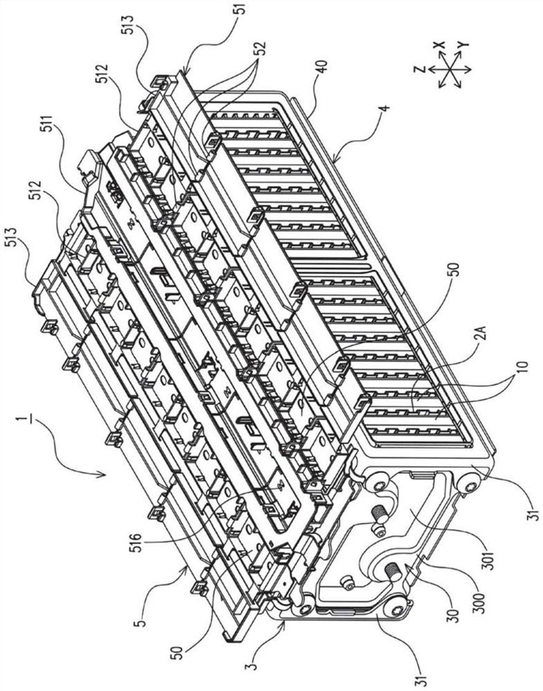
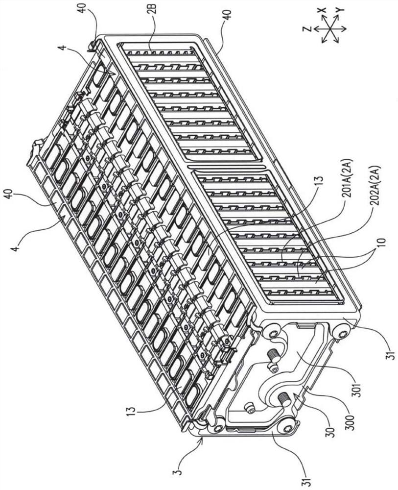
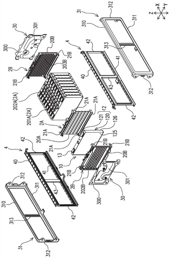
[0051] Below, refer to Figure 1 to Figure 11 , an embodiment of the present invention will be described. In addition, the name of each component (component) of this embodiment is the name of this embodiment, and it may differ from the name of each component (component) in background art.

[0052] Such as Figure 1 ~ Figure 3 As shown, the power storage device includes: a plurality of internal spacers (spacers) 2A, a power storage element 10, and a cover member 5, wherein the plurality of internal spacers 2A are arranged in a first direction (predetermined direction); 10 in the second direction orthogonal to the first direction ( figure 2The end surface in the up and down direction) has external terminals 13 and is arranged between adjacent internal spacers 2A; cover member 5 holds bus bars 50 connecting corresponding external terminals 13 to each other, and is arranged along Face extension with external terminals 13. In addition, the power storage device 1 of the present...


PUM


Abstract

An object of the present embodiment is to provide an electrical storage device capable of suppressing dimensional variations at various positions, and a cover member used for the electrical storage device. This embodiment includes: a spacer; a plurality of storage elements arranged in a first direction with the spacer and having external terminals; a cover member holding a bus bar connected to the external terminals and extending along the storage elements The spacer has a first connecting portion connecting the cover member at its end in the second direction, and the cover member has a second connecting portion that is connected to the first connecting portion in a state where movement in a direction away from the spacer is restricted. A connecting part is engaged.

Description

technical field [0001] The present invention relates to an electricity storage device including an electricity storage element, and a cover member for covering the electricity storage element in the electricity storage device. Background technique [0002] Conventionally, a power supply device including a bus bar module is known (see Patent Document 1). Specifically, such as Figure 14 As shown, the power supply device has a battery assembly 602 and a bus bar module 610, wherein the battery assembly 602 is composed of a plurality of square batteries 601 arranged in a row, and the bus bar module 610 is installed on the upper surface of the battery assembly 602 . [0003] Each of the plurality of batteries 601 has a positive electrode 603 and a negative electrode 604 at both ends in the width direction of the upper surface. In the battery assembly 602 , the positive electrodes 603 and the negative electrodes 604 are arranged alternately in a straight line in two rows along t...

Claims


Application Information

Patent Timeline
Patent Type & Authority Patents(China)
IPC IPC(8): H01M50/204H01M50/207H01M50/505H01M50/507H01M50/258H01M50/284H01M50/209H01M50/262H01M50/291H01M50/50H01M50/503
CPCH01M50/50H01M50/291H01M50/262H01M50/503H01M50/507H01M50/209H01G11/08H01G11/10H01G11/76H01G11/82Y02E60/10
Inventor 岁冈芳昌寺口直
Owner GS YUASA INT LTD
Why Eureka
Try Eureka