Amplifier with variable gain and high dynamic range

A high dynamic range, differential amplifier technology, applied in the direction of gain control, improving the amplifier to reduce nonlinear distortion, amplification control, etc., can solve the problems of increasing circuit complexity, increasing components, increasing cost, etc., to improve the dynamic range , The effect of simplifying the circuit

Inactive Publication Date: 2009-07-01
IND TECH RES INST
View PDF3 Cites 23 Cited by
  • Summary
  • Abstract
  • Description
  • Claims
  • Application Information

AI Technical Summary

Problems solved by technology

At this time, the required components will increase, the cost will ...

Method used


Image

  • Amplifier with variable gain and high dynamic range
  • Amplifier with variable gain and high dynamic range
  • Amplifier with variable gain and high dynamic range

Examples


Embodiment Construction

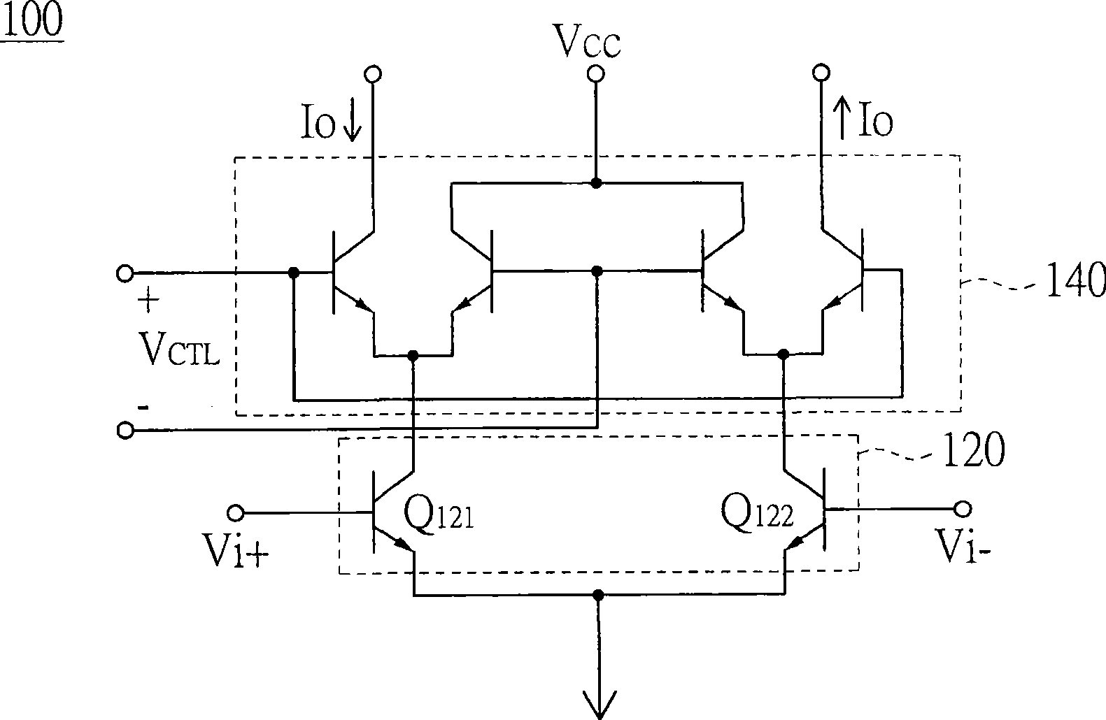
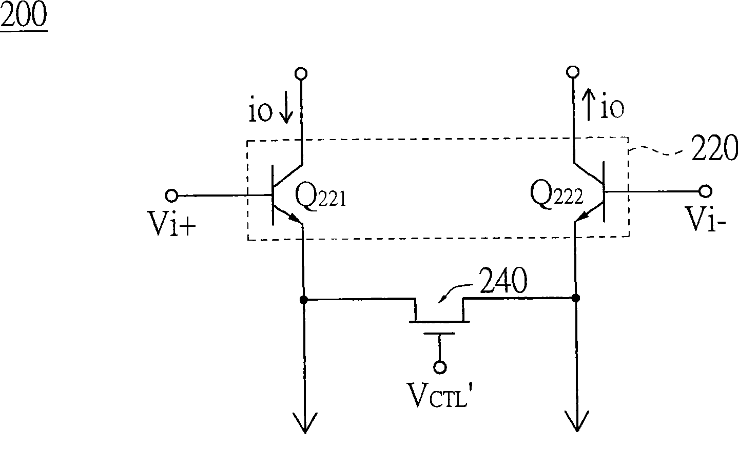
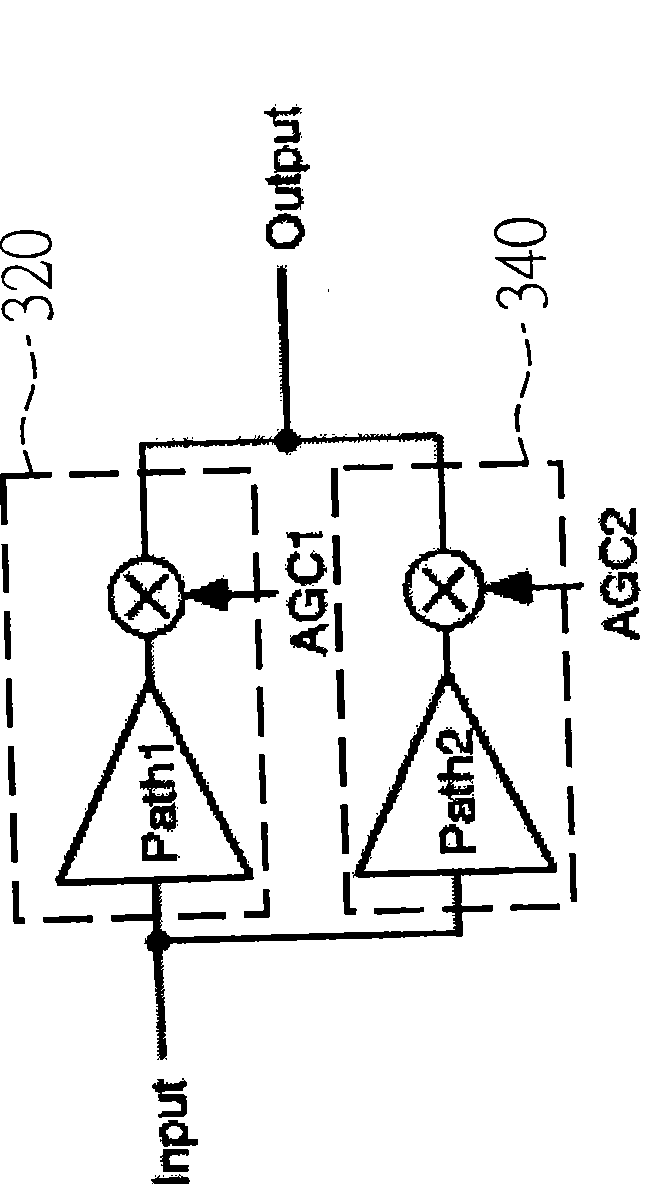
[0081] The variable gain high dynamic range amplifier of the present invention includes an amplifier module, a control unit and an output current adjustment circuit. The amplifier module is used to amplify an input signal. The amplifier module includes a plurality of amplifier units connected in parallel, and the gain values ​​of the amplifier units are different. The control unit is used for enabling at least one of the amplifier units according to a gain control signal. The enabled at least one amplifier unit is used to output a current signal in response to the input signal. The output current adjustment circuit is used for receiving the current signal output from at least one enabled amplifier unit, and under the control of the control unit, adjusts the magnitude of the current signal to output an output signal correspondingly. Each amplifier unit is coupled in series with the output current adjustment circuit.

[0082] In order to make the above content of the present ...


PUM


Abstract

A high dynamic range amplifier with variable gain comprises an amplifier module, a control unit and a circuit for regulating output current capacity. The amplifier module is used for amplifying an input signal and consists of a plurality of amplifier units which are coupled with each other in parallel and have different gain values; the control unit is used for enabling at least one amplifier unit according to a gain control signal, and at least one enabled amplifier unit is used for responding to the input signal to output a current signal; the circuit for regulating output current capacity is used for receiving a current signal output by at least one enabled amplifier unit and regulating the strength of the current signal under the control of the control unit to output an output signal correspondingly, wherein, each of the amplifier units is coupled with the circuit for regulating output current capacity in series.

Description

technical field [0001] The present invention relates to an amplifier, and more particularly to a variable gain high dynamic range amplifier. Background technique [0002] In the field of communication, receivers used to receive signals often use dynamic amplifiers to amplify the received signals. When the amplitude of the received input signal changes, the gain of the dynamic amplifier will change accordingly to maintain the magnitude of the output signal. [0003] Please refer to figure 1 , which shows the circuit diagram of a conventional dynamic amplifier using a current steering circuit. The dynamic amplifier 100 uses a current driver 140 to control the signal V CTL to adjust the gain of the dynamic amplifier 100. When the amplitude of the input signal Vi becomes larger, the control signal V CTL The voltage will go lower to reduce the output current i o to reduce the gain of the dynamic amplifier 100. However, when the amplitude of the input signal Vi is too large...

Claims


Application Information

Patent Timeline
IPC IPC(8): H03G3/30H03G1/04H03F1/32
Inventor 李青峰
Owner IND TECH RES INST
Why Eureka
Try Eureka