Screen device

A technology for barriers and installation frames, which can be used in door/window protection devices, shutters/movable grilles, buildings, etc., and can solve the problems of barrier 2 replacement, etc.

Active Publication Date: 2009-07-01
METACO INC
View PDF1 Cites 5 Cited by
  • Summary
  • Abstract
  • Description
  • Claims
  • Application Information

AI Technical Summary

Problems solved by technology

Since the pulling out of the sliding guide frame portion 3 and the wiring of the barrier tension member 15 cannot be performed at the installation position of the barrier device, the barrier device can only be replaced by removing the barrier device as a whole and transporting it to the assembly factory.
In this way, the replacement of barrier 2 takes a lot of effort

Method used


Image

  • Screen device
  • Screen device
  • Screen device

Examples


Embodiment Construction

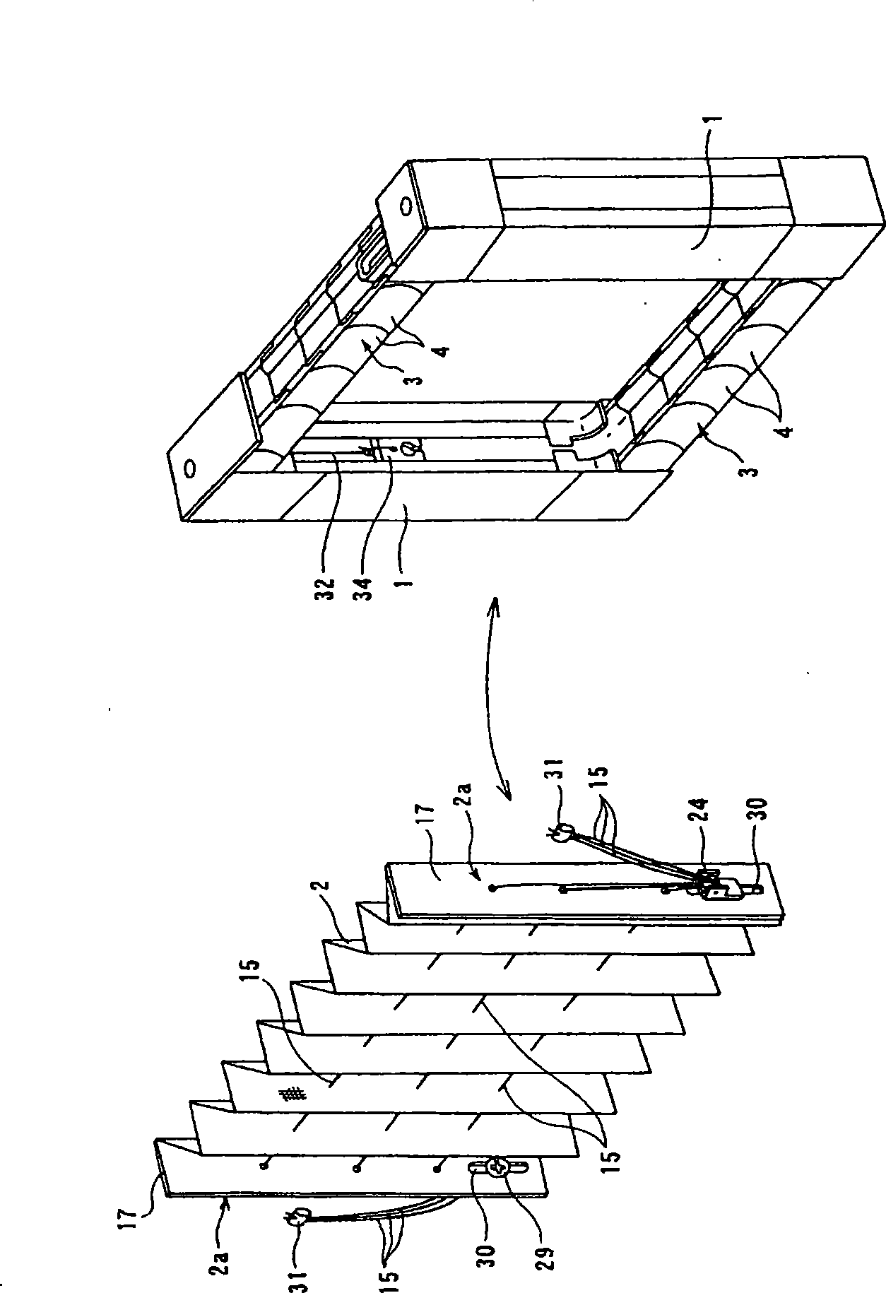
[0035] exist figure 1 and figure 2 shown in the barrier device, with Figure 11 The same reference numerals are used for the same parts of the barrier device shown, and the description thereof is omitted.

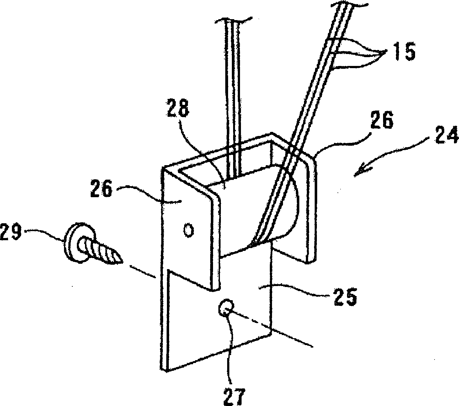
[0036] The barrier 2 is formed of a cloth, mesh, sheet, etc. with a plurality of pleats that freely shrinks and unfolds into an accordion shape. On the barrier 2, three barrier tension members 15 that penetrate the barrier 2 in the longitudinal direction are arranged at the top, bottom and center. As the barrier tension member 15, for example, ropes, wires, etc., can be used to generate tension, support the barrier 2, ensure self-support, and improve surface strength. The number of roots can be appropriately set according to the height of the barrier 2, and can be set to a plurality of two or more.

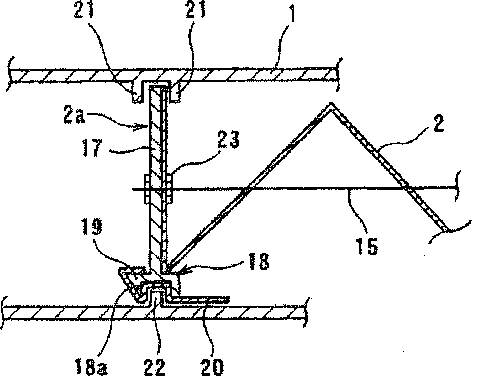
[0037] In addition, the barrier 2 is detachably attached to the barrier mounting frame portion 1 . On the outer sides of the mounting portions 2 a at the left and right ...


PUM


Abstract

A screen is detachable from a screen mounting frame part. Screen tension members extend through the screen in its length direction at plural positions. A first connector is fitted to the ends of screen tension members at one side thereof where the screen tension members are pulled out from the screen. The ends of the screen tension members are connected to a slide guide frame part at a position near the free end of the frame part. A second connector is fitted to end of a jump member at the other side where the jump member is pulled out to the screen mounting side. The first connector and the second connector are detachable, and the screen can be replaced in such a state that the slide guide frame part is pulled out from the screen mounting frame part.

Description

technical field [0001] The present invention relates to a barrier device capable of replacing a barrier when it is polluted or damaged. Background technique [0002] As a device for eliminating installation constraints when using shading and dimming mechanisms such as curtains and blinds, screens, partitions, etc., or achieving excellent operability and shape stability of barriers, the applicant provides Figure 7 and Figure 8 The barrier device shown (Patent Document 1). [0003] The barrier device has a pair of barrier installation frame parts 1 arranged opposite each other and at least one of them can slide and move. On the two barrier installation frame parts 1, a barrier 2 can be freely contracted and expanded to be installed between the two barrier installation frame parts 1 . The barrier 2 is formed of cloth, mesh, sheet, etc., and shrinks and expands with the sliding movement of at least one of the barrier mounting frame parts 1 . The barrier 2 is preferably provi...

Claims


Application Information

Patent Timeline
Patent Type & Authority Applications(China)
IPC IPC(8): E06B9/262E06B3/92E06B9/02E06B9/52
CPCE06B2009/2625E06B9/52E06B9/262
Inventor 冈地康文西冈雄一朗
Owner METACO INC
Why Eureka
Try Eureka