
Compact spinning method

A compact spinning, yarn hole technology, applied in spinning machine, yarn, textile and papermaking, etc., can solve the problem of large power consumption, and achieve the effect of improving production efficiency, good evenness and less hairiness

Active Publication Date: 2009-07-08
江阴市华方新技术科研有限公司
View PDF0 Cites 13 Cited by
  • Summary
  • Abstract
  • Description
  • Claims
  • Application Information

AI Technical Summary

Problems solved by technology

This spinning method consumes a lot of manpower and electric energy.

Method used


Image

  • Compact spinning method
  • Compact spinning method

Examples


Embodiment Construction

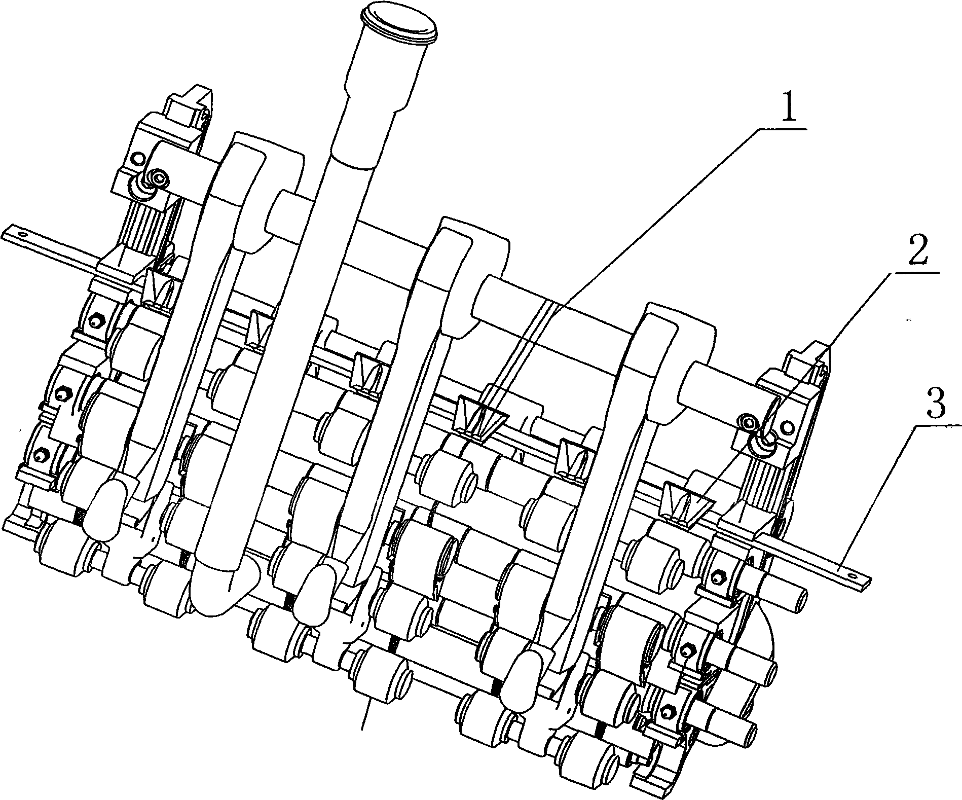
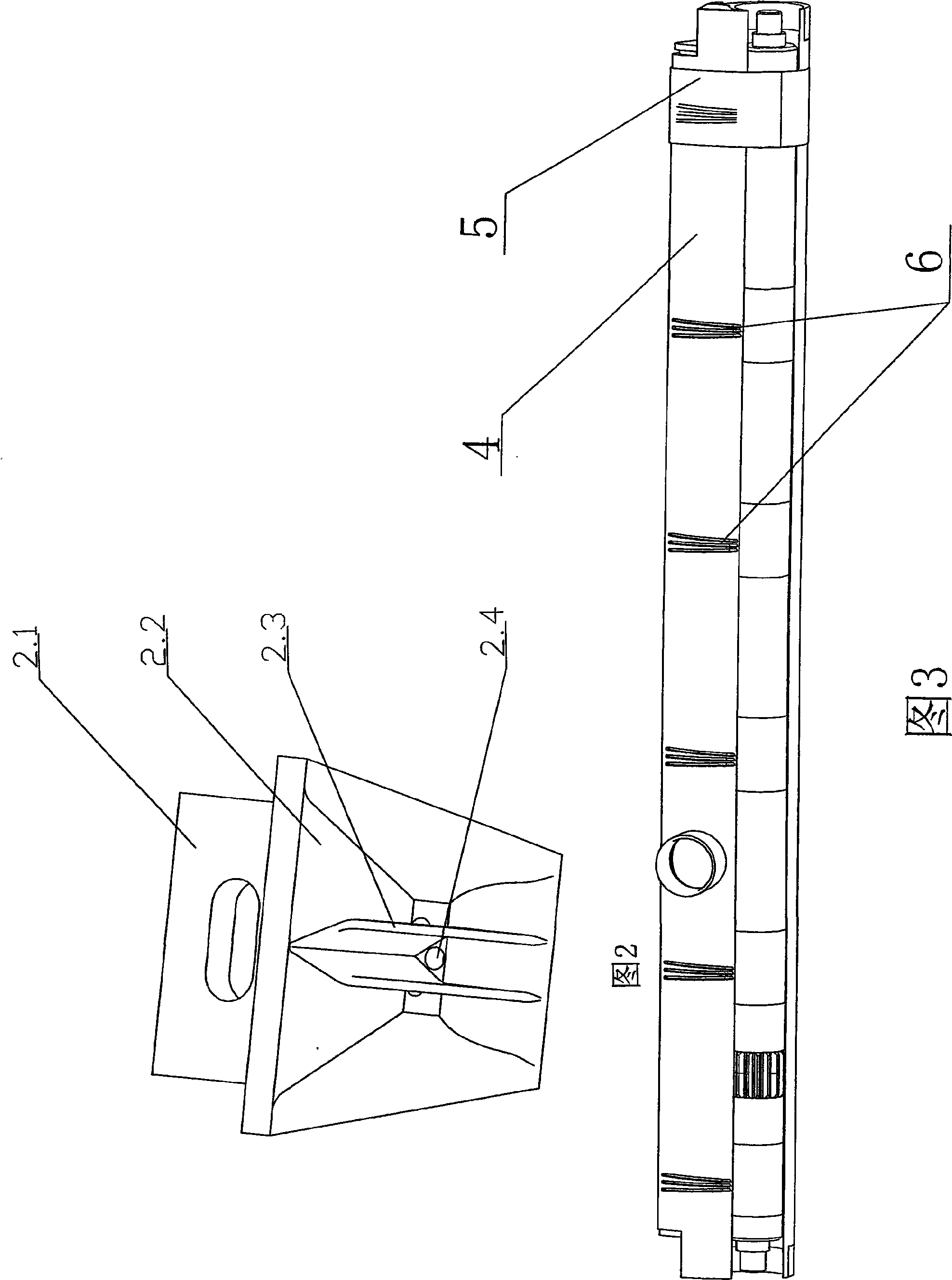
[0015] see figure 1 , the compact spinning spinning method that the present invention relates to, it is that three rovings 1 are simultaneously fed into a three-hole bell mouth 2 in parallel at the same time, and then pass through the rear roller, middle roller, front roller and compact spinning device of the spinning frame, in the described Under the action of the three airflow guide grooves 6 and the grid ring 5 on the special-shaped tube 4 of the compact spinning device, the three rovings are formed into compact spun yarns, and are automatically twisted and paralleled on the special-shaped tube 4, and the three rovings are Combined into one, that is, strands are formed, and the three airflow guide grooves on the special-shaped tube can control three yarns respectively.

[0016] The three-hole bell mouth 2 is a square cone-shaped bell mouth. The three-hole bell mouth 2 includes a square-cone-shaped bell-mouth main body 2.2. The yarn hole 2.4 is provided with two partitions ...


PUM


Abstract

The invention relates to a method for compact spinning which includes steps as follows: three rovings are feed into a pipe socket with three holes parallelly synchronously, then three rovings passes through a back roller, a middle roller, a front roller and a compact spinning device, three rovings forms a compact spinning thread acted by three airflow conduit ferrules on a special pipe of the compact spinning device and a net ring, the compact spinning thread processes twisting and doubling automatically, three rovings becomes a roving for forming folded yarn. The method has advantages of economize on manpower and reducing energy consumption.

Description

(1) Technical field [0001] The invention relates to a spinning method using compact spinning, in particular to a yarn forming method of strands. It belongs to the technical field of spinning. (2) Background technology [0002] The traditional roving single feed into the compact spinning device of the spinning frame must go through two-for-one twisting, doubling and other processes to meet the basic requirements of strand products. This spinning method is all bigger to the consumption of manpower, electric energy etc. (3) Contents of the invention [0003] The purpose of the present invention is to overcome the above disadvantages and provide a compact spinning method that saves manpower and energy consumption. [0004] The object of the present invention is achieved like this: a kind of compact spinning spinning method is to feed three rovings into a three-hole bell mouth in parallel at the same time, and then pass through the back roller, middle roller, front roller and...

Claims


Application Information

Patent Timeline
IPC IPC(8): D02G3/28D01H5/70D01H7/02D01H13/04
Inventor 唐正永张红梅陈开
Owner 江阴市华方新技术科研有限公司
Learn More