Smoke discharging system with automatic air draft speed regulation function according to smog concentration

A smoke exhaust system and automatic adjustment technology, which can be used in ventilation systems, heating and ventilation control systems, heating and ventilation safety systems, etc., and can solve problems such as automatic adjustment of suction power

Inactive Publication Date: 2009-07-08
张国胜
View PDF1 Cites 13 Cited by
  • Summary
  • Abstract
  • Description
  • Claims
  • Application Information

AI Technical Summary

Problems solved by technology

In this solution, the physical sensor senses the speed of the hot air flow, and the chemical receptor senses the gas concentration, not the concentration of oil fume itself. Therefore, there is no smoke exhaust system that automatically adjusts the draft according to the smoke concentration in the prior art

Method used


Image

  • Smoke discharging system with automatic air draft speed regulation function according to smog concentration
  • Smoke discharging system with automatic air draft speed regulation function according to smog concentration
  • Smoke discharging system with automatic air draft speed regulation function according to smog concentration

Examples


Embodiment 1

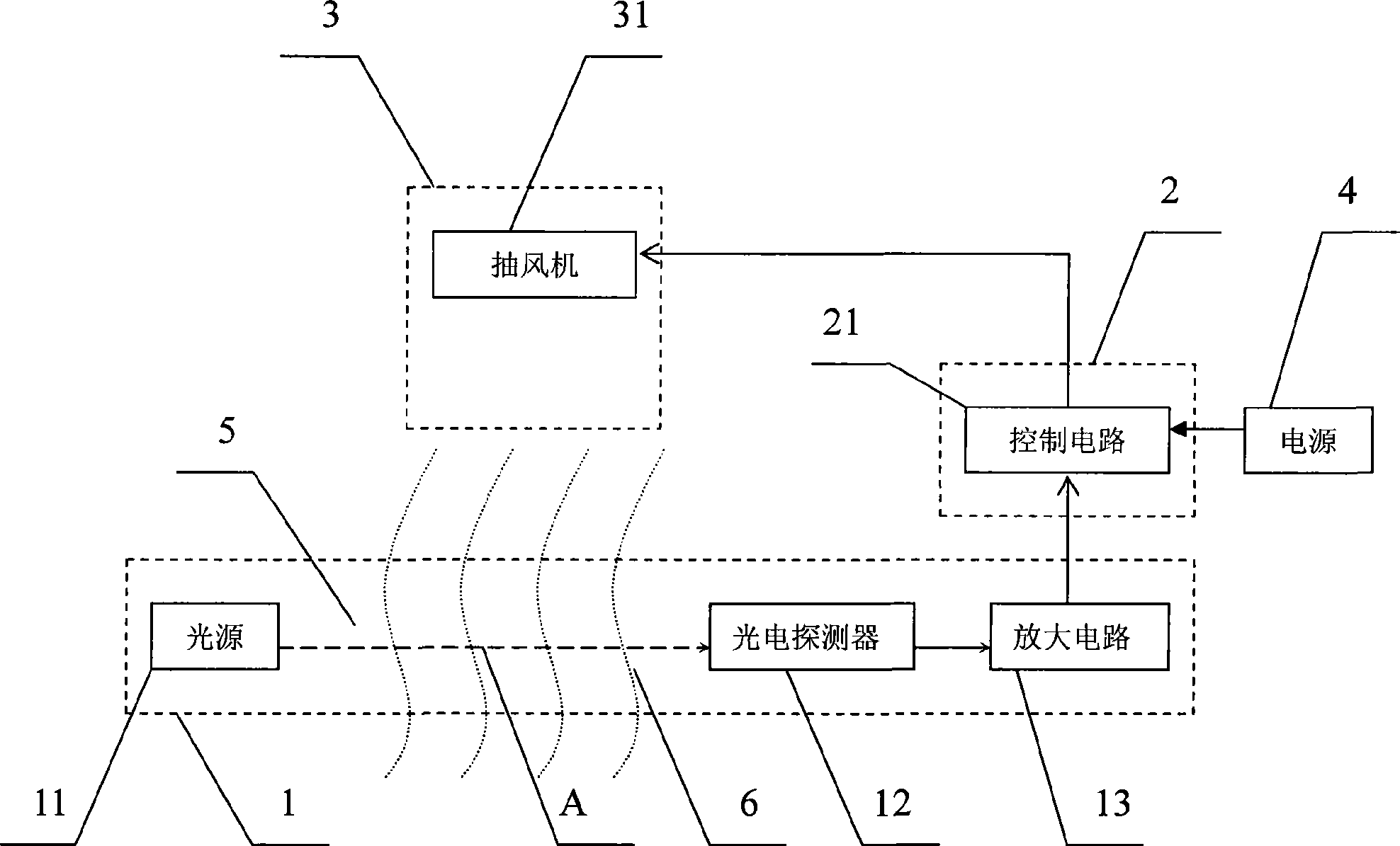
[0031] A smoke exhaust system that can automatically adjust the wind speed according to the smoke concentration, including a photoelectric detection unit 1, a fan speed control unit 2, an exhaust device 3 and a power supply 4, the output end of the photoelectric detection unit 1 is connected to the fan speed control unit 2, and the fan speed The control unit 2 is connected with the ventilation device 3 and the power supply 4 .

[0032]The photodetection unit 1 includes a light source 11, a photodetector 12, and an amplifying circuit 13 whose magnification matches the photodetector 12. There is a space 5 between the light source 11 and the photodetector 12, and the smoke 6 passes through the space 5 to reach the ventilation device 3. The light beam A generated by the light source 11 is consistent with the photodetector 12 in spectral characteristics; the photodetector 12 is connected to the amplifier circuit 13, the light beam A generated by the light source 11 passes through th...

Embodiment 2

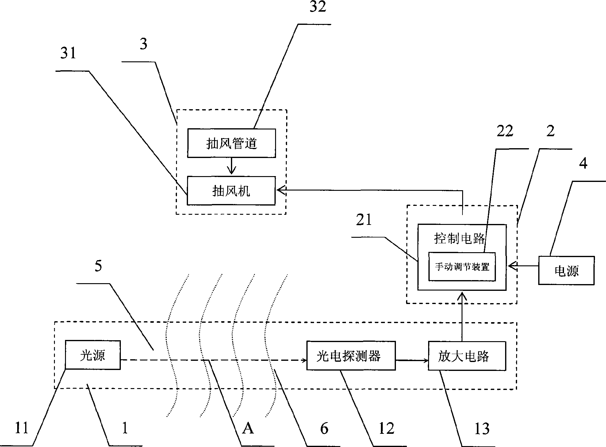
[0038] Embodiment 2 has basically the same structure as Embodiment 1, except that a manual adjustment device 22 is added to the fan speed control unit 2 , and the manual adjustment device 22 is set in the control circuit 21 and located in the operational amplifier of the control circuit 21 .

[0039] The exhaust device 3 includes a motor-driven exhaust fan 31 and an exhaust duct 32 .

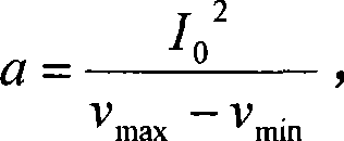
[0040] The control circuit 21 controls the draft speed of the draft device 3 by controlling the input current of the draft device 3 according to the output value v of the photoelectric detection unit 1, so the monotonically decreasing function relation I about the current is input in the operational amplifier 2 = b-av or I 2 = b-alnv.

[0041] The manual adjustment device 22 includes two adjustment devices in the control circuit 21 , one of which adjusts the constant coefficient a, and the other adjusts the constant coefficient b, so as to adjust the suction speed of the exhaust fan according t...


PUM


Abstract

The invention relates to a fume exhaust system capable of adjusting the air exhausting speed according to the fume concentration, which comprises an air exhausting device and a power supply, and is characterized by further comprising a photoelectric detection unit, a blower rotating speed control unit, wherein the output end of the photoelectric detection unit is connected with the blower rotating speed control unit which is connected with a power supply, and the output end of the blower rotating speed control unit is connected with the air exhausting device simultaneously. The fume exhaust system makes use of the principle that the light absorption by the fume and the reflection effect cause the attenuation of light intensity, adopts a photoelectric detection method to measure the fume concentration, and converts the changes of the fume concentration into electric signals to be output to the blower rotating speed control unit so that the blower rotating speed control unit adjusts the rotating speed of the air exhausting device according to the changes of the fume concentration, thereby achieving the aim of adjusting the air exhausting speed automatically according to the fume concentration. The fume exhaust system has the advantages of electricity conservation and labor conservation, high fume exhausting efficiency, and low cost.

Description

technical field [0001] The invention relates to a smoke exhaust system, in particular to a smoke exhaust system which can automatically adjust the drafting speed according to the smoke concentration. Background technique [0002] The smoke exhaust system can be used in many occasions, such as range hoods in household kitchens, and exhaust fans in smoking rooms. The faster the suction speed, the greater the suction force, and the higher the removal rate of smoke or oil fume. But the technology that the exhaust velocity of smoke exhaust system is connected with the smoke density of this occasion has not been seen yet. For example, range hoods are generally provided with several fixed gears on the casing panel, and the wind speed generated by the fan blades of the range hood is manually adjusted, thereby changing the suction force of the range hood on the range hood. This design brings some inconvenience to the user. When both hands of the user are occupied, the wind speed ca...

Claims


Application Information

Patent Timeline
Patent Type & Authority Applications(China)
IPC IPC(8): F24C15/20F24F7/007F24F11/02
Inventor 张国胜
Owner 张国胜
Why Eureka
Try Eureka