Retro-reflection device

A technology of retro-reflector and reflective layer, which is applied in the direction of instruments, optical components, optics, etc., to achieve the effect of beautiful appearance, reasonable structure design and reduced possibility

Active Publication Date: 2011-06-01
SATE LITE FOSHAN PLASTICS
View PDF0 Cites 0 Cited by
  • Summary
  • Abstract
  • Description
  • Claims
  • Application Information

AI Technical Summary

Problems solved by technology

However, the convex ribs on the surface of the product will reduce the reflective intensity required by the standard at an observation angle of 0.2 degrees or 0.333 degrees, and at the same time affect the appearance of the product and because the mold is relatively hard during the process of embossing the concave ribs, the punch for embossing the concave ribs is harder. , the hard material is relatively brittle, and the concave rib is relatively small, so the punch in the process of pressing the concave rib is easy to break and damage the mold. Another major disadvantage is that after the convex rib is formed in the light-transmitting layer of the retro-reflector, the cross-section of the convex rib is Isosceles triangle, no matter how it is placed, it has a certain direction. When installing the retro-reflector, there are strict requirements on the installation position of the convex edge, so that the refracted light can only be observed at an angle of 1.5 degrees. For users, this It is ignorant, so even if there is a retro-reflector installed on the product, there will be no reflective effect due to installation errors, which is very unsafe for users. This point is more prominent for disc-shaped retro-reflectors. Therefore, the current European ECE standard requires circular retro-reflectors to meet the standard 1.5-degree observation angle reflection requirements at any angle of 360-degree rotation, so that it will be difficult for the reflection requirements with an observation angle of 1.5 degrees to pass through directional convex ribs. Meet the requirements of the spin test

Method used


Image

  • Retro-reflection device
  • Retro-reflection device
  • Retro-reflection device

Examples


Embodiment 1

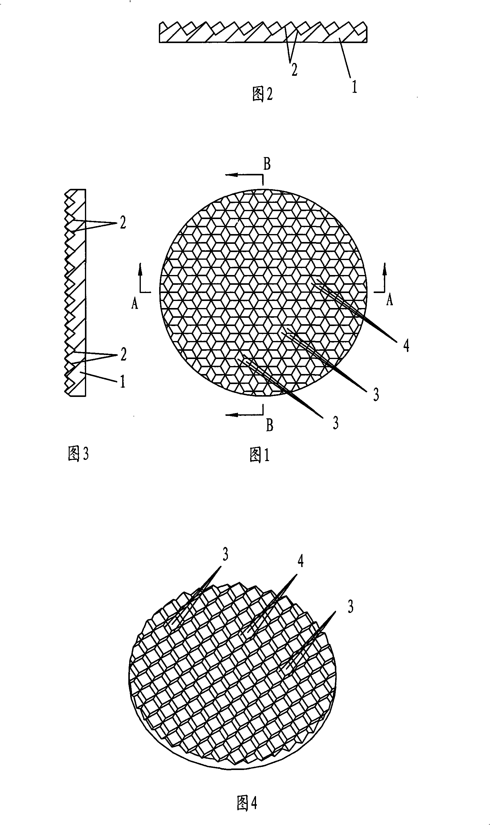
[0027] Embodiment 1, in conjunction with Fig. 1 to Fig. 4, a disc-shaped retro-reflector with an area of ​​28.3 square centimeters comprises a light-transmitting layer 1 and a reflective layer 2, and the reflective layer 2 consists of 111 corner cubes with an observation angle of 0.2 degrees 3 and 12 corner cubes 4 with an observation angle of 1.5 degrees are arranged in an array, and the corner cube 3 makes the angle between the refracted light refracted from the light-transmitting layer and the incident light before entering the light-transmitting layer be 0.2 degrees, and 1.5 degrees to observe The corner cube prism 4 of angle makes the angle between the refracted light rays refracted out from the light-transmitting layer 1 and the incident light rays before entering the light-transmitting layer 1 be 1.5 degrees, and the angle between the two adjacent reflection surfaces of the corner cube prism 4 with an observation angle of 1.5 degrees is 88.15-88.75 degrees. In the above...

Embodiment 2

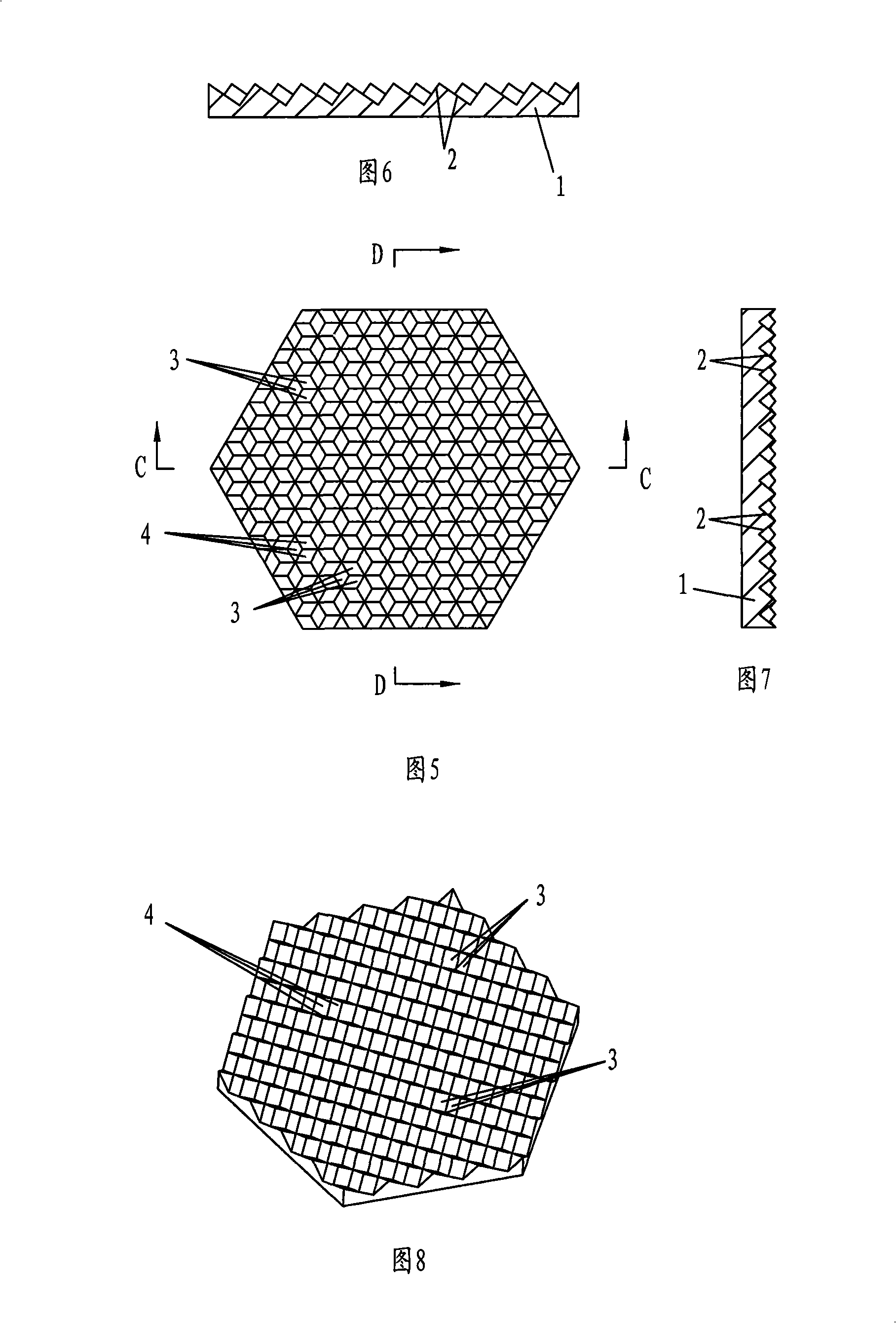
[0070] Embodiment 2, in conjunction with Fig. 5 to Fig. 8, a kind of area is the hexagonal plate retro-reflector of 28.4 square centimeters, comprises light-transmitting layer 1 and reflective layer 2, and reflective layer 2 is made of 122 pyramids by 0.333 degree viewing angle The prism 3 and the corner cube prism 4 arranged in an array by 12 1.5 degree observation angles, the corner cube prism 3 makes the angle between the refracted light refracted from the light-transmitting layer 1 and the incident light before entering the light-transmitting layer 1 be 0.333 degree, The corner cube prism 4 with an observation angle of 1.5 degrees makes the angle between the refracted light refracted from the light-transmitting layer 1 and the incident light before entering the light-transmitting layer 1 be 1.5 degrees, and the corner cube prism 4 with an observation angle of 1.5 degrees has two adjacent reflective surfaces The included angle is 88.15-88.75 degrees. In the above angle rang...


PUM


Abstract

The invention relates to a light-reflecting warning device, in particular to a reflex reflector. The reflex reflector comprises a euphotic layer and a reflecting layer, wherein the reflecting layer is formed by corner cube prisms with a 0.2-degree observation angle which are arranged in arrays, the corner cube prisms form a 0.2-degree included angle between refracted rays refracted from the euphotic layer and the incident rays before entering the euphotic layer, corner cube prisms with a 1.5-degree observation angle are also distributed in the corner cube prism arrays to form a 1.5-degree included angle between the refracted rays refracted from the euphotic layer and the incident rays before entering the euphotic layer, and the included angle of two adjacent reflecting surfaces of the corner cube prisms with a 1.5-degree observation angle is 88.15 to 88.75 DEG. The reflex reflector is reasonable in structural design. The mould of the reflex reflector can be processed simply without pressing concave ribs on the surface of a mould cavity and damaging the mould. All observation angles meet the requirements for compulsory-standard light intensity. And the possibility that a user is impacted is reduced.

Description

technical field [0001] The invention relates to a reflective warning device, in particular to a retro-reflector. Background technique [0002] Plastic retro-reflectors are mainly used in traffic safety warning signs such as bicycles, motorcycles, automobile rear lights and highways. Existing retro-reflectors are all injection molded by high-precision molds. A qualified retro-reflector requires light The refracted light refracted by the retro-reflector must meet the mandatory standard when the observation angle (the angle between the incident light and the refracted light) is 0.2 degrees and 1.5 degrees (or 0.333 degrees and 1.5 degrees). The existing retro-reflection The light refracted by the incident light through the retro-reflector satisfies the reflection intensity in the range of 0.2 degrees (or 0.333 degrees) at the observation angle. Secondary refraction is achieved by reflecting back at a small reflection angle. [0003] As for the refracted light reflected by th...

Claims


Application Information

Patent Timeline
Patent Type & Authority Patents(China)
IPC IPC(8): G02B5/122
Inventor 李晓彬刘常升韩海斌朱彧唐显仕
Owner SATE LITE FOSHAN PLASTICS
Why Eureka
Try Eureka