Planar display

A flat-panel display and display panel technology, which is applied to instruments, signal transmission systems, electrical components, etc., can solve the problems of increasing the production cost of the flat-panel display 10, and achieve the effect of saving production costs.

Inactive Publication Date: 2009-07-08
CORETRONIC
View PDF0 Cites 0 Cited by
  • Summary
  • Abstract
  • Description
  • Claims
  • Application Information

AI Technical Summary

Problems solved by technology

However, the use of these conductive materials for grounding will result in an increase in the manufacturing cost of the flat panel display 10

Method used


Image

  • Planar display
  • Planar display
  • Planar display

Examples


Embodiment Construction

[0033] The foregoing and other technical contents, features and effects of the present invention will be clearly presented in the following detailed description of preferred embodiments with reference to the drawings. The directional terms mentioned in the following embodiments, such as: up, down, left, right, front or back, etc., are only referring to the directions attached to the drawings. Accordingly, the directional terms are used to illustrate and not to limit the invention.

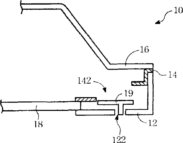
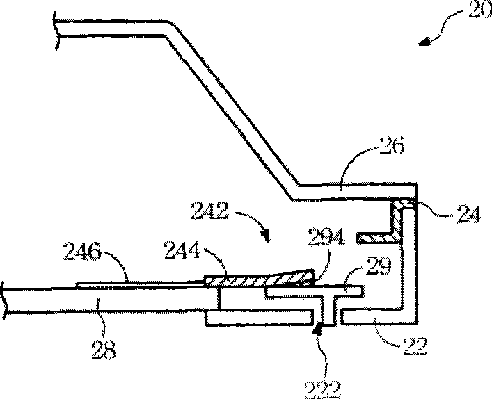
[0034] image 3 It is a schematic cross-sectional view of a flat panel display 20 according to a preferred embodiment of the present invention. In this embodiment, a plasma display is taken as an example for illustration. As shown in the figure, the flat panel display 20 has a display panel 28 , a front plastic frame 22 , an infrared module 29 , a metal front frame 24 and a rear cover 26 . Wherein, the horizontally bent section of the front rubber frame 22 extends to the front of the display pan...


PUM


Abstract

The invention discloses a flat-panel display comprising a display panel, a front rubber frame, an infrared module, a metal front frame and a rear cover, wherein, the front rubber frame extends to the front of the display panel, thereby defining a display area for the display panel, and moreover, the front rubber frame is provided with a receiving hole and at least two positioning poles arranged on sides of the receiving hole; the front of the infrared module is exposed to the receiving hole and is positioned behind the receiving hole after penetrating the positioning poles on the sides of the receiving hole, while, the back of the infrared module is provided with at least an earthing point; the metal front frame is arranged behind the front rubber frame and surrounds the display panel; the metal front frame is provided with at least a long shrapnel which is pressed on the earthing point of the infrared module, so that the infrared module is earthed and is fixed on the positioning poles; and the rear cover is arranged behind the metal front frame and the display panel. The invention can not only skip the use of copper foil or conductive foam but also maintain good electromagnetic shielding effect at the same time without changing the design of a traditional infrared module.

Description

technical field [0001] The invention relates to a flat display, in particular to a flat display with an infrared receiver. Background technique [0002] Generally speaking, displays that play TV programs or movies have the function of wireless remote control. The function of this wireless remote control is usually realized by way of infrared remote control. That is, an infrared receiver is provided in the display, and the user uses the infrared transmitter to emit preset infrared signals to control the operation of the display, such as channel switching, volume adjustment, power switch, and the like. [0003] figure 1 is a schematic diagram of a typical flat panel display 10 . As shown in the figure, the flat panel display 10 has a front plastic frame 12 , a metal front frame 14 , a rear cover 16 , a display panel 18 and an infrared module 19 . Wherein, the horizontally bent section of the front rubber frame 12 extends to the front of the display panel 18 . The front be...

Claims


Application Information

Patent Timeline
Patent Type & Authority Applications(China)
IPC IPC(8): G09F9/313H05K5/00H05K9/00G08C23/04
Inventor 张国原
Owner CORETRONIC
Why Eureka
Try Eureka