Energy saving control circuit for LED lamp
A technology of LED lamps and energy-saving control, which is applied in the direction of energy-saving control technology, lamp circuit layout, circuit layout, etc., and can solve the problem that the channel current cannot be cut off.
- Summary
- Abstract
- Description
- Claims
- Application Information
AI Technical Summary
Problems solved by technology
Method used
Image

Examples
Embodiment 1
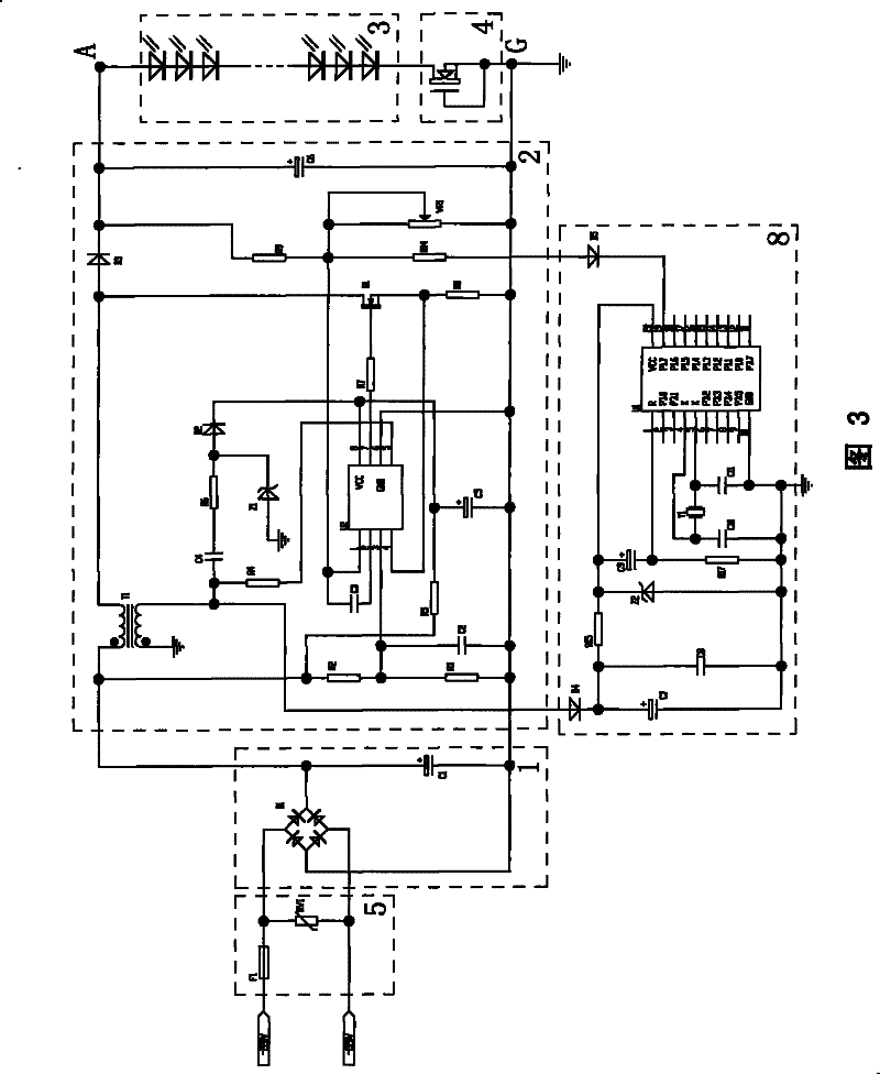
[0025] Such as image 3As shown, the energy-saving control circuit of LED lamps in this embodiment includes a rectification and filtering circuit 1, a voltage stabilizing circuit 2, an LED load 3, a constant current source device 4, a short circuit protection circuit 5, and a timing circuit 8. The alternating current passes through the rectification and filtering circuit 1 After rectification and filtering to become direct current, the voltage is stabilized by the voltage stabilizing circuit 2 to become a constant voltage direct current output to form an output terminal A and a ground terminal G, and the LED load 3 and the constant current source device 4 are connected in series A loop is formed between the output terminal A and the ground terminal G, and the timing circuit 8 is connected to the voltage stabilizing circuit 2 for providing a timing feedback signal to the voltage stabilizing circuit 2 to change the The output voltage of voltage regulator circuit 2. The rectific...
Embodiment 2
[0035] Such as Figure 4 As shown, the difference between this embodiment and Embodiment 1 is that: the LED lamp of this embodiment also includes a cooling fan, and this embodiment also includes a fan circuit 6 for supplying power to the cooling fan of the LED lamp, and the LED load 3 includes Four groups of several LEDs in series, each group of LEDs are connected in series with one of the constant current source devices 4, and the four groups in series are then connected in parallel as a whole with the fan circuit 6 in series and connected to the Between the output terminal A and the ground terminal G, so there are four constant current source devices 4 in this embodiment. In this embodiment, the number of several LEDs connected in series should depend on the voltage V of the output terminal of the voltage stabilizing circuit 2. 0 , the voltage V across the constant current source device 4 D , the voltage V across the fan circuit 6 Fan and the average turn-on voltage V of ...
Embodiment 3
[0039] Such as Figure 5 As shown, the difference between this embodiment and Embodiment 2 is that: the LED load 3 of this embodiment includes four groups of several LEDs connected in series, each group of LEDs is connected in parallel and then connected with the constant current source as a whole The device 4 is connected in series and connected between the output terminal A and the ground terminal G, that is, there is only one constant current source device 4 in this embodiment; The transformer T1 in the voltage circuit 2 takes a tap to provide it with 5-12V DC power supply, that is, the fan circuit 6 in this embodiment is powered separately from the LED load 3 and the constant current source device 4 . Likewise, the power consumption of the constant current source device 4 and the fan circuit 6 accounts for a small proportion of the entire circuit, and the power supply efficiency of the entire circuit is very high.
[0040] The other features of this embodiment are the sam...
PUM
 Abstract
Description
Claims
Application Information
 - R&D
- Intellectual Property
- Life Sciences
- Materials
- Tech Scout
- Unparalleled Data Quality
- Higher Quality Content
- 60% Fewer Hallucinations
Browse by: Latest US Patents, China's latest patents, Technical Efficacy Thesaurus, Application Domain, Technology Topic, Popular Technical Reports.
© 2025 PatSnap. All rights reserved.Legal|Privacy policy|Modern Slavery Act Transparency Statement|Sitemap|About US| Contact US: help@patsnap.com