Method and device for producing a screw connection point

A threaded connection and part technology, which is applied in the direction of welding equipment, resistance welding equipment, manufacturing tools, etc., can solve the problem of damage to the threaded connection part, etc., and achieve the effects of easy forming and processing, tight guidance, and high processing accuracy

Inactive Publication Date: 2009-07-08
DAIMLER AG
View PDF1 Cites 0 Cited by
  • Summary
  • Abstract
  • Description
  • Claims
  • Application Information

AI Technical Summary

Problems solved by technology

In this case the threaded connection will be damaged

Method used


Image

  • Method and device for producing a screw connection point
  • Method and device for producing a screw connection point
  • Method and device for producing a screw connection point

Examples


Embodiment Construction

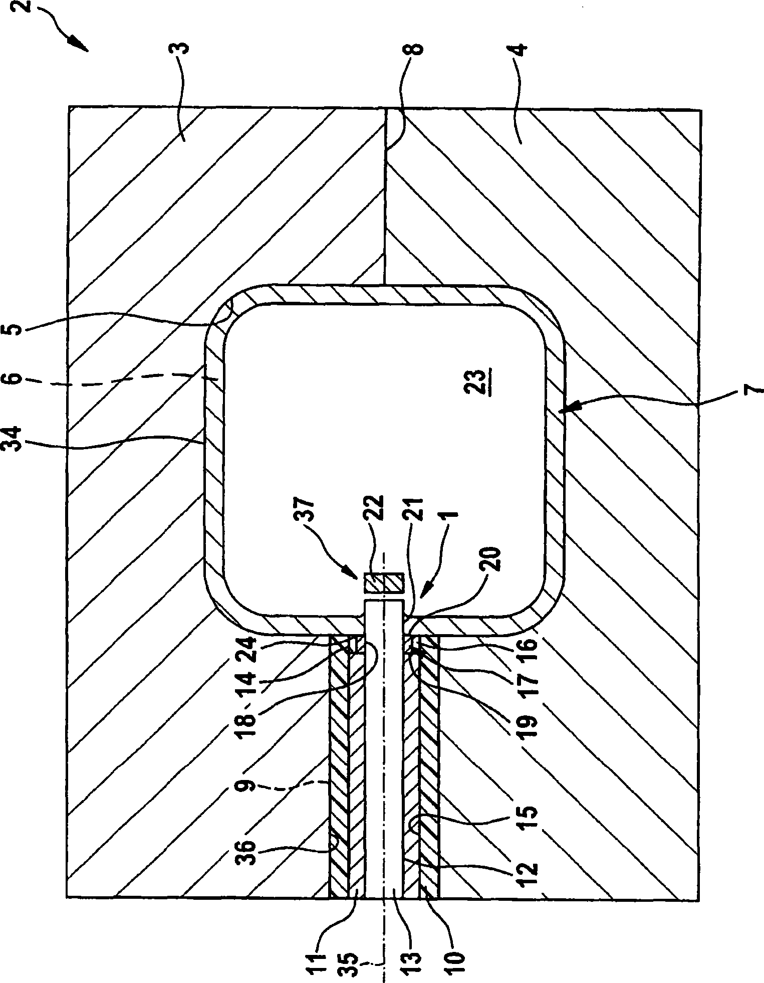
[0020] figure 1A device for producing the screw connection 1 on the periphery 34 of the hollow profile 7 is shown. The device includes a hydraulic forming tool 2, and the internal high pressure forming mold includes an upper mold 3 and a lower mold 4. On the sides of the molds 3 and 4 facing each other, a mold cavity 5 is processed, which defines a mold cavity 6 when the mold 2 is closed, that is, when the upper mold 3 and the lower mold 4 are attached. A hollow profile 7 is accommodated in this cavity 6 for forming and punching. Formed in the mutually facing sides of the upper mold 3 and the lower mold 4 is a guide hole 9 whose axis 35 lies in the plane of the boundary 8 of the two molds 3 and 4 . The guide bore 9 extends from the hydroforming tool 2 on the one hand and leads into the mold cavity 5 of the forming tool 2 on the other hand. Inserted into the guide hole 9 is an electrically insulating sleeve 10 which extends over the entire guide hole 9 and rests against its ...


PUM


Abstract

The invention relates to a method and a device for producing a screw connection point (1) on the periphery (34) of a hollow section (7), that is expanded by a high-pressure fluid. An attachment (17, 31) comprising a bore (18) with an inner thread is mounted on the hollow section (7) in the hydroforming mould (2) and a hole is then made in the hollow section (7) in alignment with the bore (18). The aim of the invention is to produce a durable screw connection point (1) on the periphery (34) of a hollow section (7) in a simple and reliable process. To achieve this, the attachment (17, 31) is advanced towards the hollow section (7) with the aid of an electrode (11, 30) that is integrated into the hydroforming mould (2). The attachment (17, 31) is resistance welded to the hollow section (7) by means of the electrode (11, 30), once said attachment has been placed on the mould relief (5) in the vicinity of the screw connection point (1) to be created.

Description

technical field [0001] The invention relates to a method for producing a screw connection according to the preamble of claim 1 and a device for carrying out the method according to the preamble of claim 7 . Background technique [0002] A method of this type and an apparatus of this type are known from DE 197 33 477 A1. In this case, a punch is embedded in the hydroforming tool, which has a central bore in which a stamping punch is guided. The free end of the stamping punch extends beyond the end of the punch which receives it, wherein an attachment with a through-opening is screwed onto the end of the stamping punch. In the non-use position of the stamping punch, this free end is closed flush with the side of the attachment facing away from the punch. The punch is partially movable within a pilot bore of the hydraulic forming tool which opens into a forming tool cavity defining a cavity. A hollow profile blank is placed in this cavity, which expands / expands by the creati...

Claims


Application Information

Patent Timeline
Patent Type & Authority Applications(China)
IPC IPC(8): B21D26/02B23K11/00B21D28/28B21D26/035
CPCB21D28/28B23K11/004B23K11/3081B21D26/035
Inventor K-U·杜齐亚克J·法尔克D·格拉夫J·克尔恩S·朗瓦尔德R·马滕斯J·舒尔特K-U·杜齐亚克
Owner DAIMLER AG
Why Eureka
Try Eureka