Method for manufacturing flexible optical plates, and flexible optical plate manufactured by utilizing same and backlight module

A manufacturing method and backlight module technology, applied in the direction of optics, optical components, semiconductor devices of light-emitting components, etc., can solve problems such as excessive processing size, processing defects, and inability to reach the processing size, so as to improve quality and accuracy, The effect of reducing manufacturing and equipment costs

Inactive Publication Date: 2011-09-28
锺震桂
View PDF6 Cites 11 Cited by
  • Summary
  • Abstract
  • Description
  • Claims
  • Application Information

AI Technical Summary

Problems solved by technology

On the other hand, when the optical plate is used as a light guide plate, the size of its microstructure is in the range of about 100 microns, so the development of a smaller processing size can help improve the resolution, while the general carbon dioxide laser processing The size is about 200 to 300 microns, and cannot meet the requirements of processing sizes smaller than 100 microns or smaller
Therefore, the current carbon dioxide laser processing technology has the disadvantages of large processing size and processing defects, and cannot be effectively applied to the manufacture of microstructures of optical plates such as light guide plates.

Method used


Image

  • Method for manufacturing flexible optical plates, and flexible optical plate manufactured by utilizing same and backlight module
  • Method for manufacturing flexible optical plates, and flexible optical plate manufactured by utilizing same and backlight module
  • Method for manufacturing flexible optical plates, and flexible optical plate manufactured by utilizing same and backlight module

Examples


Embodiment Construction

[0034] The aforementioned and other technical content, features and effects of the present invention are described in detail in conjunction with the accompanying drawings.

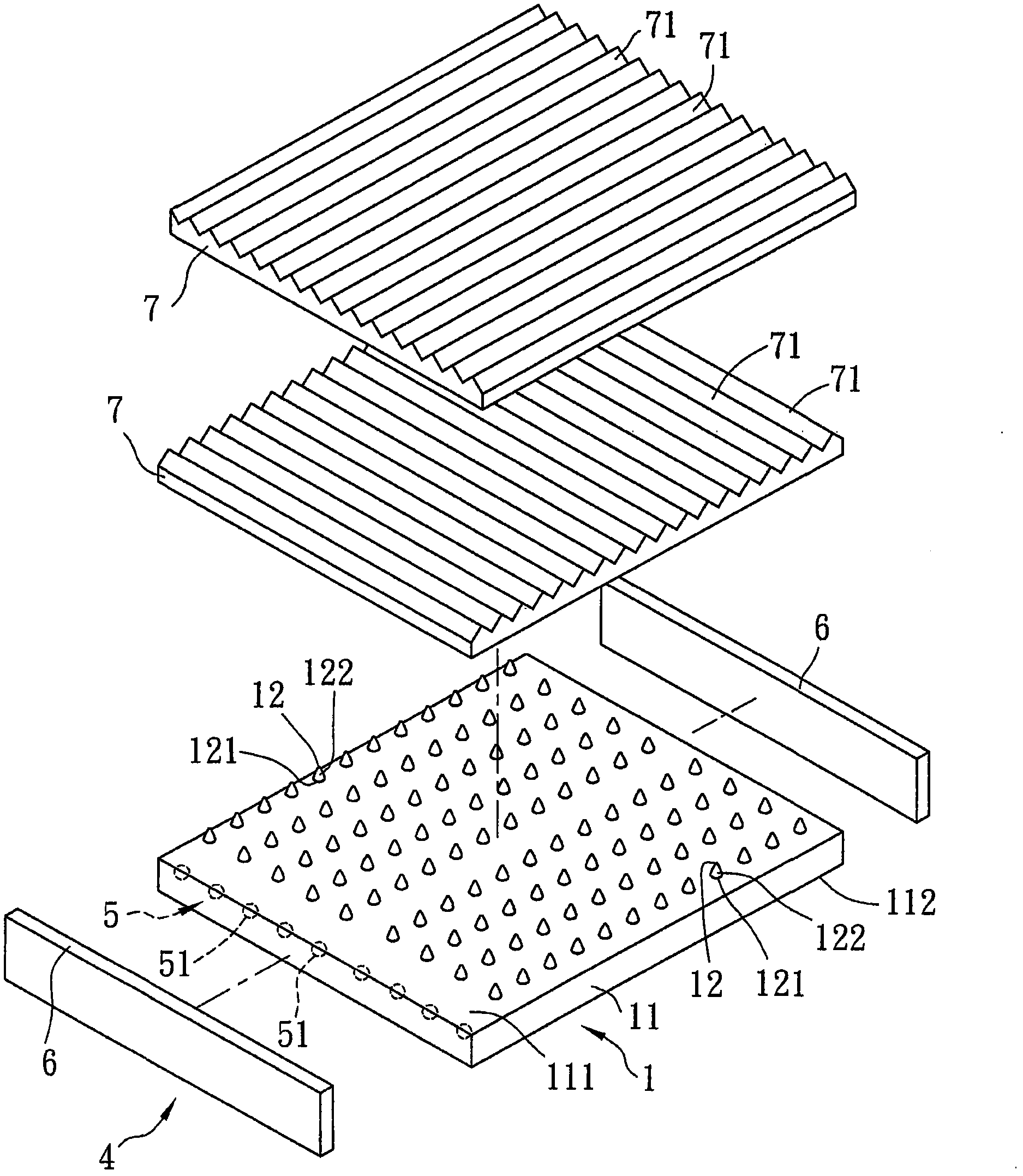
[0035] refer to figure 1 , 2 , is a preferred embodiment of the backlight module 4 of the present invention, which can be used to provide a uniform planar light source for a display panel (not shown in the figure). The backlight module 4 includes: a flexible optical plate 1 , a light emitting unit 5 , two reflective plates 6 and two brightening sheets 7 each having a plurality of prism structures 71 arranged in parallel.

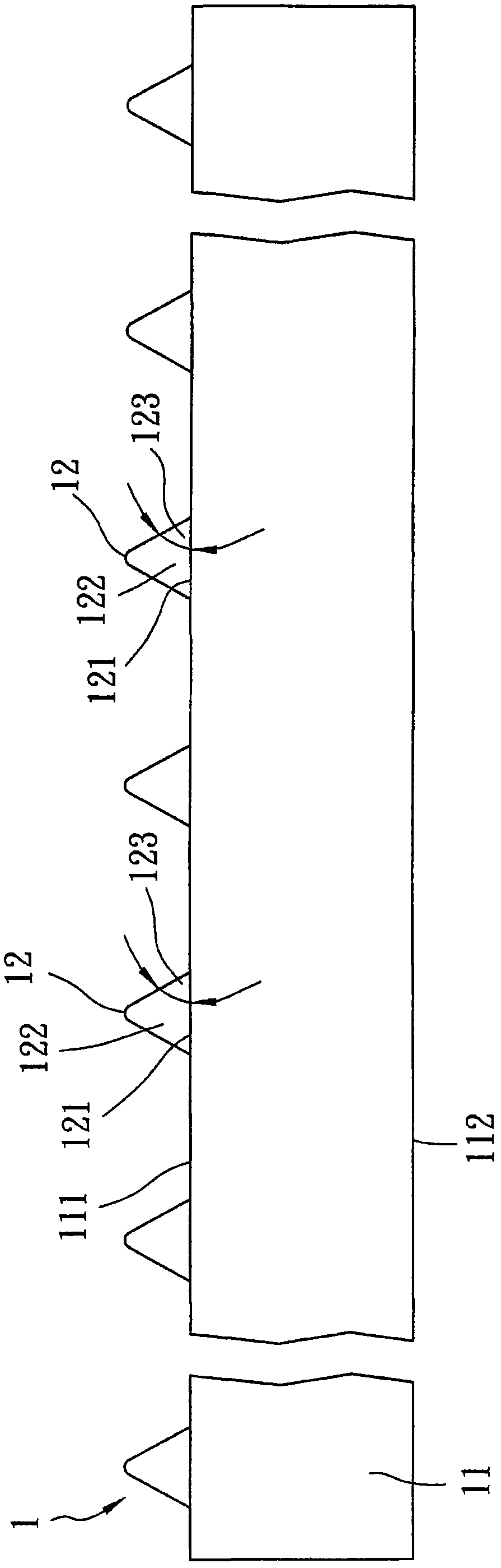
[0036] The flexible optical plate 1 is used as a light guide plate in this embodiment, and it includes a base material 11 and several microstructures 12 located on the base material 11 . Wherein, the substrate 11 has a first light-transmitting surface 111 and a second light-transmitting surface 112 spaced apart from the first light-transmitting surface 111 . The microstructures 12 pro...


PUM

PropertyMeasurementUnit
sizeaaaaaaaaaa

Abstract

The invention discloses a method for manufacturing flexible optical plates, a flexible optical plate manufactured by utilizing the same and a backlight module. The method comprises the following steps: forming a plurality of microstructured mold cavities on the mold surface of a master mold substrate by using a carbon dioxide laser and a photomask made of a metal material; cladding a high polymer material on the mold surface; and finally, baking and drying the polymer material, thus forming the flexible optical plate. The photomask is high in thermal conductivity and can cover part of the carbon dioxide laser, so that the sizes of the microstructured mold cavities can be less than that of the focusing light spot of the carbon dioxide laser, and the production of a heat affected zone on the mode surface can be avoided, therefore the effects that the processing size of the flexible optical plate is less than 100 microns and the production of processing defects is avoided can be achieved.

Description

technical field [0001] The invention relates to a method for manufacturing a flexible optical plate, the flexible optical plate and a backlight module produced by the method. Background technique [0002] Today's products emphasize humanization and mobility, making freely rollable and portable electronic products gradually become the mainstream, and in order to adapt to various usage environments, flexible displays have gradually become indispensable devices. [0003] However, the display usually includes several optical plates with different functions, such as: light guide plate, diffuser plate; taking the optical plate as a light guide plate as an example, in order to make the optical plate guide light uniformly, a protrusion is formed on the surface of the optical plate microstructure. In general, the manufacturing methods of optical plates with microstructures mostly use lithography to define the microstructures, such as the manufacturing method disclosed in Taiwan Inve...

Claims


Application Information

Patent Timeline
Patent Type & Authority Applications(China)
IPC IPC(8): G02B6/00G02B5/02F21S8/00F21V13/00F21Y101/02F21Y115/10
Inventor 锺震桂郑智擎林士隆许原杰佘坤霖
Owner 锺震桂
Why Eureka
Try Eureka