Temporary bridge

一种临时桥、桥元件的技术,应用在桥梁、桥梁形式、轻便式桥等方向,能够解决冲突区域易受伤、跨越系统不是独立等问题

Inactive Publication Date: 2009-07-08
ETAB A DESCHAMPS & FILS
View PDF1 Cites 14 Cited by
  • Summary
  • Abstract
  • Description
  • Claims
  • Application Information

AI Technical Summary

Problems solved by technology

[0008] [08] Finally, these spanning systems of the prior art are not self-contained and require the presence of service personnel, who are thus exposed and vulnerable, for example in conflict areas

Method used


Image

  • Temporary bridge
  • Temporary bridge
  • Temporary bridge

Examples


Embodiment Construction

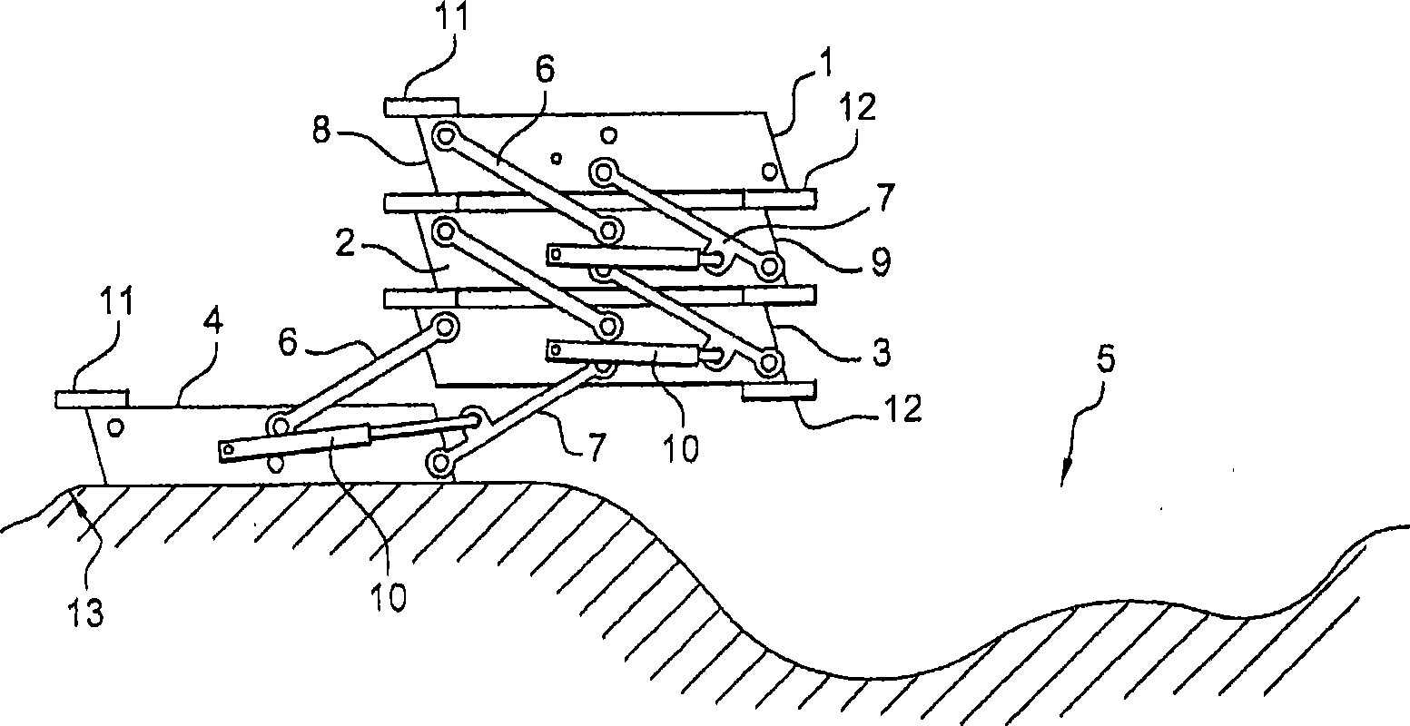
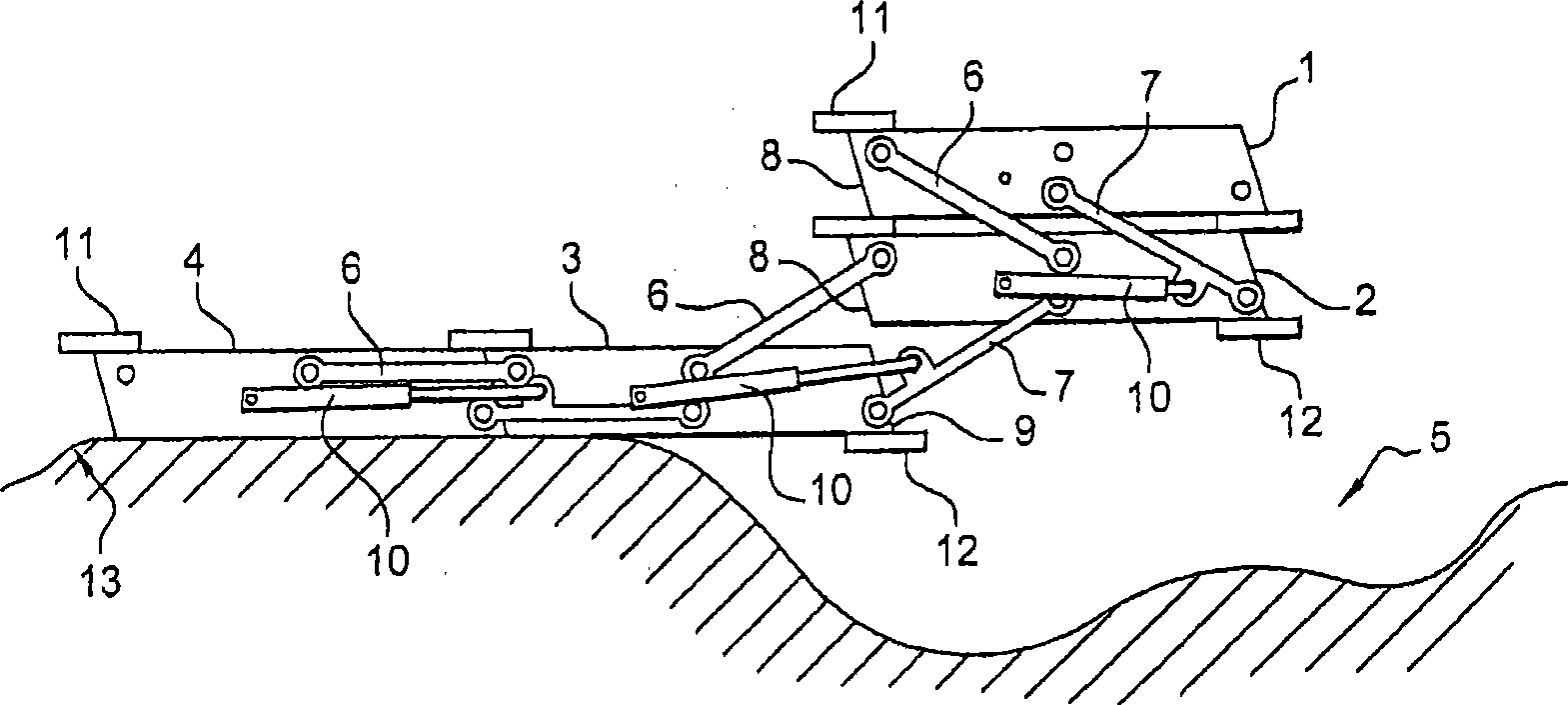
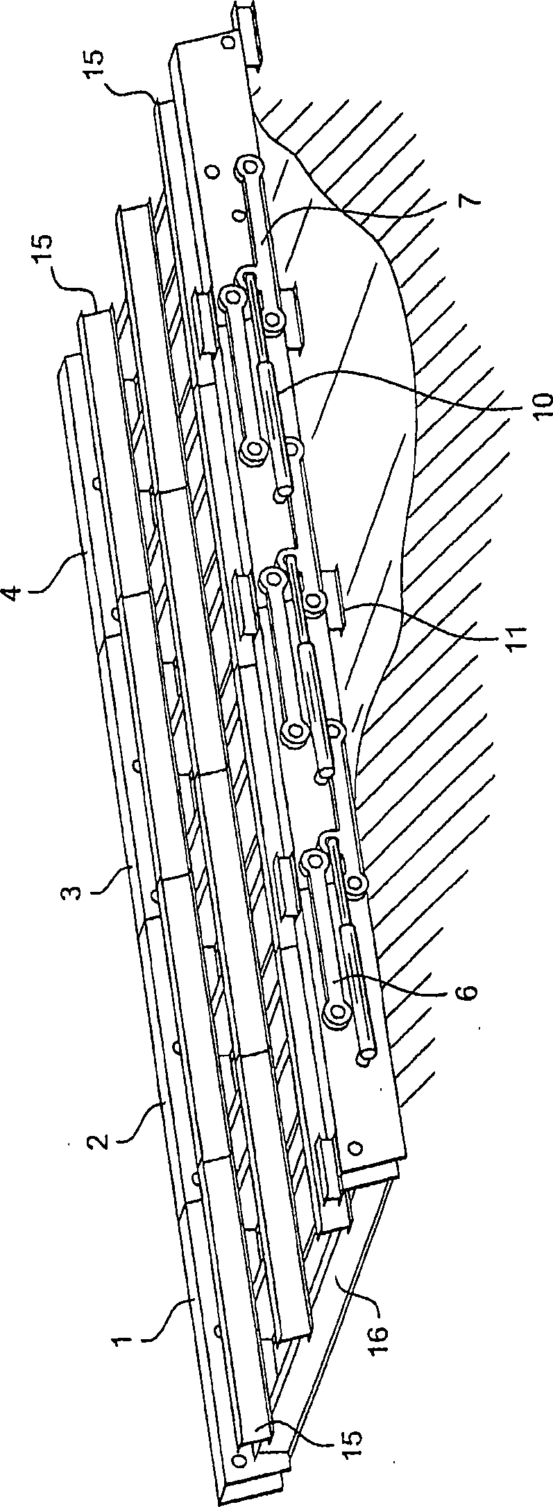
[0091] [91] figure 1 The temporary bridge is shown in an undeployed position according to a first embodiment of the invention. The temporary bridge comprises four bridge elements 1-4 which are stacked so as to form a vertical stack and are articulated relative to each other.

[0092] [92] Advantageously, the bridge elements 1-4 are detachably connected to each other, so that the length of the bridge can be changed and adapted to the gap 5 to be spanned.

[0093] [93] Each bridge element is connected to a single piece 1, 4 forming the end of the bridge, or to two other bridge elements 2, 3 by two pairs of connecting arms, each Both sides of these bridge elements 1-4 (only one single piece is shown for clarity). Each of these arm pairs includes two parallel arms 6, 7 mounted laterally on the bridge elements 1-4, the ends of which are movable in rotation so as to allow movement of the bridge elements 1-4. relatively mobile.

[0094] [94] These parallel arms assume the shape o...


PUM


Abstract

The invention concerns a temporary bridge, including bridge components (1-4), intended to be stacked when said bridge is in a non-deployed position. According to the invention, these bridge components (1-4) comprise moveable pieces relative to the others. Each bridge component, on at least one of its ends, includes a mating face (8, 9), which can cooperate with the mating face of another bridge component, in a manner that allows these bridge elements (1-4) to be assembled when they are placed end to end. The bridge includes displacers for each of the bridge components, superposed on another component of the bridge in the first so-called non-deployed position and in the second so-called deployed, position, where the mating faces (8, 9) of said bridge component and said other bridge component are placed facing one another and combined together. It also includes an inner track, related or otherwise.

Description

technical field [0001] [01] The present invention relates to temporary bridges for crossing gaps, especially temporary bridges for the passage of pedestrians, cars or other motorized equipment. Background technique [0002] [02] Such temporary bridges that allow spanning gaps by means of one or more travures assembled to each other are known. [0003] [03] However, the transport and deployment of these luggage racks requires the use of laying equipment. The deployment system of these luggage nets is therefore particularly complex due to the simultaneous consideration of the large dimensions of these luggage nets and of the effective surface provided by the base of the laying device. In particular, the unfolding system requires a projection frame which allows positioning of said assembled luggage rack towards the front of the laying device. [0004] [04] Furthermore, the dimensions of the luggage net imposer a clear floor for the luggage net to be able to be deployed. [0...

Claims


Application Information

Patent Timeline
Patent Type & Authority Applications(China)
IPC IPC(8): E01D15/12E01D15/133
CPCE01D15/124E01D15/133E01D15/12E01D21/00
Inventor 乔治-保罗·德尚
Owner ETAB A DESCHAMPS & FILS
Why Eureka
Try Eureka